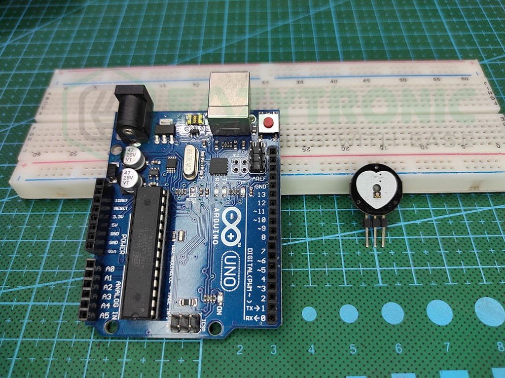
Welcome back guys, we’re back with Pulse Sensor with Arduino UNO, another exciting and straightforward article in the Arduino series. Before this, all the articles that we posted were based on sensors that can be used in various fields, but today’s one is strictly for the medical field. The pulse sensor is a low-cost Heart-Rate measuring sensor. Although, there are many advanced versions and other sensors available for more precise calculations. But for the simplest output, this is recommended. As we’re going to start, make sure to read about Pulse Sensor in detail from here. Now, let’s start the further discussion.
Pulse Sensor and Arduino in Brief
Pulse Sensor
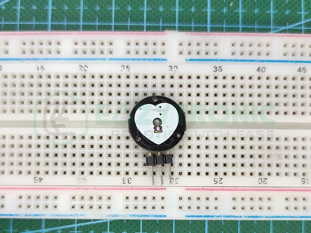
The pulse sensor is a small yet crucial sensor in the Robotics field. This sensor is not only used in various projects but also in medical equipment. However, there are new and more advanced versions related to this sensor available in the market. A pulse sensor is used to measure Heart Rate & Heart Beat, also other crucial vitals, but for this model, it is limited to this.
The pulse sensor is built out of many small components, mainly an Ambient Light Photo Sensor & Low Power Op-Amp. These two are the main components of this sensor. The sensor works on the principle of Photoplethysmogram, in simple words reflection flight from our blood.
A single color light, either RED or Green or in some advanced versions both, sends light rays into our skin. These light rays penetrate under our skin and enter into blood vessels. The light rays get reflected from our blood and as received by the Ambient light Sensor. The received light is then converted into a voltage signal, which is further adjusted into a readable/detectable range through an Op-Amp.
The output of the sensor is of a 5V logic level that can be easily read by any microcontroller. Also, the output is given via a single line that enables it to use with microcontrollers like ATTINY45, etc. On the other hand, It is recommended to use some insulation on the side of the sensor through which it makes contact with skin, as mild shock may be felt while using an AC power supply.
Arduino UNO
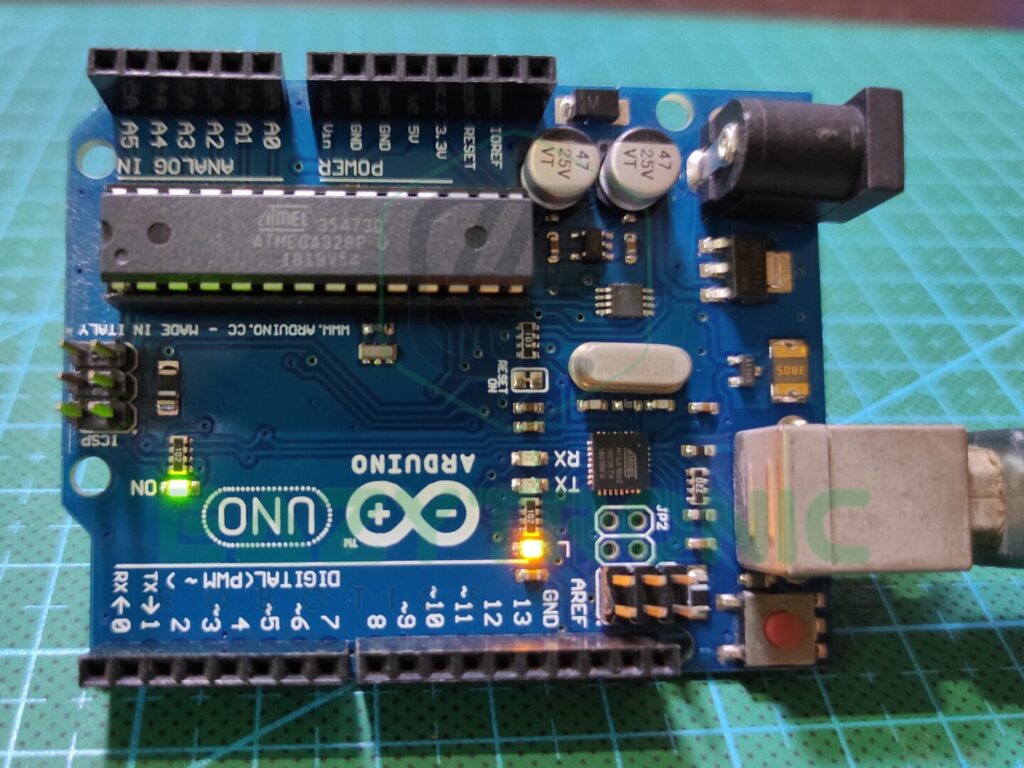
Arduino UNO is one of the simplest microcontrollers that I would recommend for beginners. This board is available very easily in the online and offline markets, and that too at a low cost. This makes it ideal as at this price point with such good configurations and advantages this is the best board for beginners.
Arduino UNO is built out of ATMEGA328PU, which is the main component of the board. Along with several other active and passive components, it makes up the Arduino UNO.ATMEGA328PU is an AVR-based CMOS Microcontroller that runs at a frequency of 16MHz. This speed is slow, but for small projects it doesn’t matter.
The IC comes in DIP-28 package that makes it easier to replace during any fault in the board. Moreover, it is packed with 2 KB of SRAM along with 32 KB of programmable flash memory. Furthermore, it comes with 1 KB of EEPROM memory that makes it useable for all kinds of program. Also, you can add external SPI flash to the board for more storage in case you need to store program code.
At last, the pins provided on the Arduino UNO board includes all the communication pins a board should have. This included 13 Digital pins that enclose SPI and Serial communications. Moreover, it also contains 6 PWM pins that we can control via code. Also, it has 6 Analog pins with 10-bit resolution. This total adds up to 23 I/O pins, including some other miscellaneous pins for other purposes.
Material Required
- Arduino UNO
- Pulse Sensor
- Bradboard
- Jumper Wires
- Tape for insulation
- A system to program Arduino.
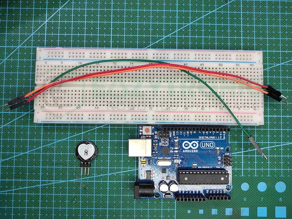
Fritzing Schematic
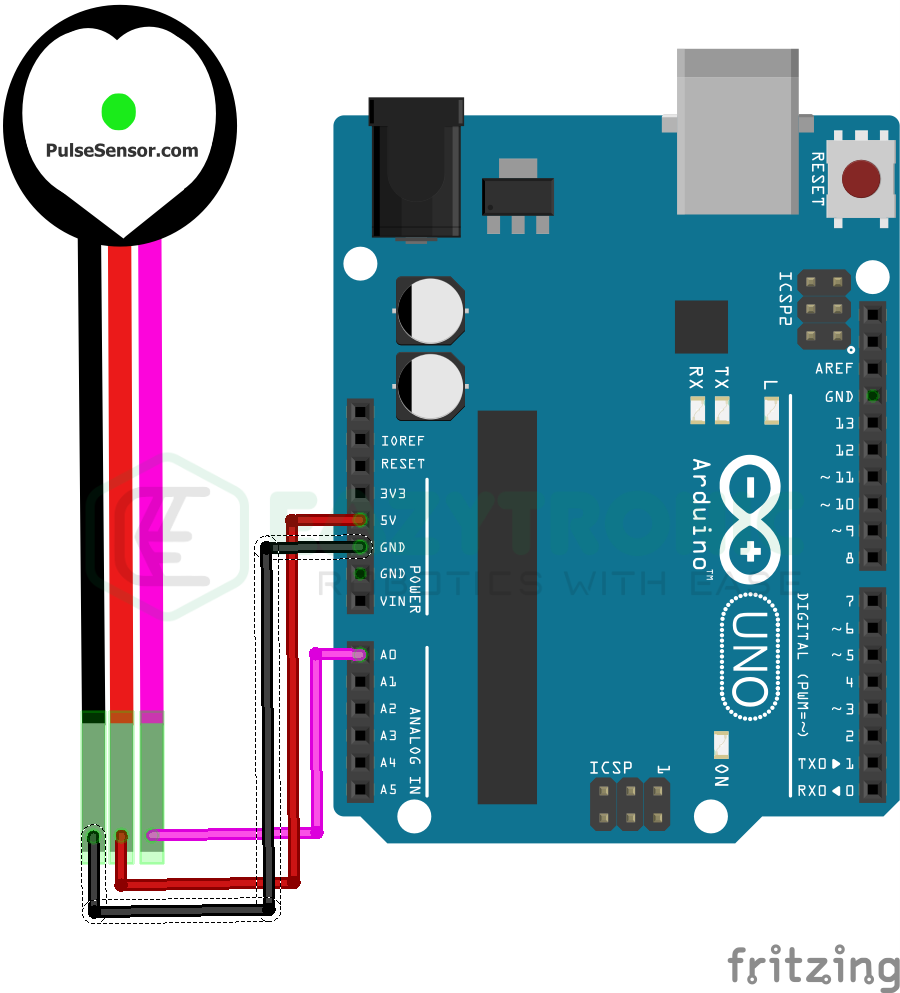
Wiring
| Arduino UNO | Pulse Sensor |
|---|---|
| 5V/3.3V | Vcc/+ |
| GND | GND/- |
| A0 | OUT/S |
Programming Arduino
Here start the important sections of the article, from here we’ll be discussing code and preparing the IDE for the Arduino UNO. First, make sure you have downloaded the Arduino IDE or updated it to the latest version possible. Also, make sure to check that it has all the libraries and Board definitions are up-to-date. Further, there are some libraries that need to be installed for the sensor to work. But before that, make sure you have some knowledge about Arduino IDE and Arduino Boards. For this, read the Arduino Introductory Article. Let’s now proceed with library installation.
Installing Library
To make the sensor work, read the value, and finally calculate Heart Rate, you need to install a library. You can install any library you want, but the one I’ll be using to demonstrate can be found here. Also, you can install this library via the in-built library manager of the Arduino IDE. Moreover, it is recommended to read the documentation there for more understanding of the working of library I process of calculation of Heart rate and other stuff.
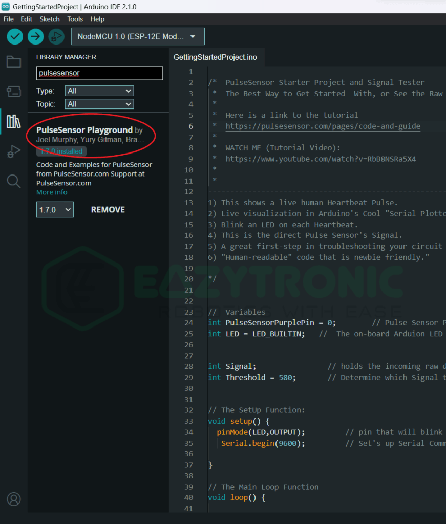
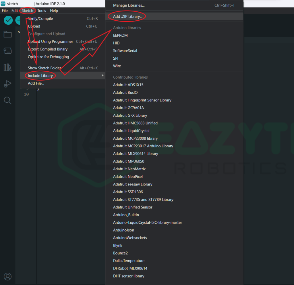
You can also download and install the library manually from the GitHub page of the library from here. Download the zip file of the library and install the library from the sketch menu. To do this, follow Sketch > Include Library > Add .ZIP Library. Also, there is an attached image below for reference.
Code
The code section of today’s article is somewhat different from other demonstrations. In today’s article, we’ll be explaining how to get the BPM from the examples provided in the library. Also, there will be two codes, one for calibration and the other for getting the Actual BPM
Calibration / Serial Plotter
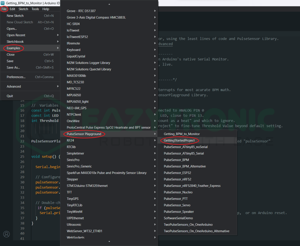
For the first code, open the examples from the file menu. Do this by File > Examples > Pulsesensor Playground > Getting Started Project. Also, there is a reference image for you to open the code. Once done, we’ll be beginning the explanation part.
Explanation
int PulseSensorPurplePin = A0;
int LED = LED_BUILTIN;


int Signal;
int Threshold = 580;
In the first four lines, we declare some variables to store some information. First, we initialize the pin to which the sensor is connected. The sensor can only be connected to an Analog Pin. While keeping this in mind, the closest pin is A0, however, you can also choose some other pin of your choice.
Next, we declare a pin for the LED as an output you can choose any pin for this but as the Arduino UNO has an on-board LED on pin 13, hence we’ll be using that. Further, we declare a variable to store the incoming signal from the Pulse sensor that can be updated every time we read data from the sensor.
Lastly, we declare a threshold value that marks the borderline for the signal about which the digital led we have connected will glow.
void setup
void setup() {
  pinMode(LED,OUTPUT);
   Serial.begin(9600);
}
In the setup section, there is nothing much to do. Therefore, we just define the pin type of the pin on which the LED is connected and start the serial communication at 9600 baudrate. You can change both of these as per your choice but, remember to make changes in further section also as per your choice.
void loop
void loop() {

  Signal = analogRead(PulseSensorPurplePin);
   Serial.println(Signal);
   if(Signal > Threshold){
     digitalWrite(LED,HIGH);
   } else {
     digitalWrite(LED,LOW);
   }
delay(10);
}
The loop section is somewhat difficult to understand, but I’ll try my best to explain it o you. In the First line, we store the incoming Analog value from the sensor to the variable we declare during the initialization part. As the signal gives the voltage signal as the output, so you need to read the voltage signal in the form of an Analog value. Further, we print the value to the serial monitor.
The condition further up is for the onboard LED to glow. It has no importance in the working of the code, but for explanation let me do it. We check the incoming value with the threshold value we have initialized first. If the incoming value is greater than that value, then the LED will glow, else it’ll remain off.
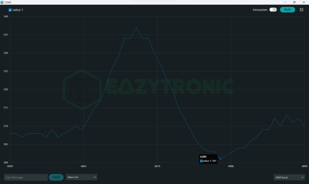
You need to note the lowest value of the sensor when your finger is on the sensor. But before this, open the serial plotter, the icon can be found on the top right. Click on it, you can see a graph of your heartbeat. Note the lowest value, as I have done in the image below. We’ll be using this value in the next code.
Heart Rate Calculation
Now we’re ready to calculate the heart rate, for this you need to open the example code just above the previous one. The Example code is named Getting BPM to Monitor. Once done, I’ll begin the explanation.
Explanation
#define USE_ARDUINO_INTERRUPTS true
#include <PulseSensorPlayground.h>


const int PulseWire = A0;
const int LED = LED_BULITIN; // replace LED_BUILTIN with 13 if it shows error
int Threshold = 500;
PulseSensorPlayground pulseSensor;
In this code, we measure the heart rate and display it on the Serial monitor. For this code to work, we need the lowest value that we have noted from the previous code. This value will act as the threshold value in this case. In the first line, we enable the low-level interrupts of Arduino UNO for the most accurate detection. This will not only mark interrupts at every beat, but also the faint signal will trigger this.
Next, we include the library for the sensor, this library is important for the code to work. Also, it can differ on the library you are using and therefore change the whole code. Further, we define some variables from the previous code. Lastly, we define or create an instance or object that points to our sensor connected at the A0 pin.
The Syntax of the line is like, PulseSensorPlayground <variable object>;. You can give any other name for the variable but make sure to change all the lines with the new variable for the code to compile.
void setup()
void setup() {
  Serial.begin(9600);
  pulseSensor.analogInput(PulseWire);
  pulseSensor.blinkOnPulse(LED);
  pulseSensor.setThreshold(Threshold);


   if (pulseSensor.begin()) {
    Serial.println("We created a pulseSensor Object !");
  }
}
Next comes the setup section, in this we define some crucial tasks to start for the sensor to print values on the serial monitor. First, we start with beginning the Serial communication at 9600 baudrate. You can change the baudrate as you want. Further, we define the pin on which the sensor is connected, followed by this we enable the built-in LED to blink in accordance with our heartbeat.
In the next line, we set the threshold that plays a major role in the whole calculation. This threshold will be taken in regard while recognizing the heartbeat. Also, this will be used in calculating the BPM. Moreover, the built-in LED will also blink corresponding to this threshold value.
Lastly, we write a statement to check for pulse sensor object creation and Arduino can read a signal. For this, the statement <variable>.begin(), will either return true or false. With this, the condition will print the confirmation statement.
void loop()
void loop() {

if (pulseSensor.sawStartOfBeat()) {
int myBPM = pulseSensor.getBeatsPerMinute();
 Serial.println("♥  A HeartBeat Happened ! ");
 Serial.print("BPM: ");
 Serial.println(myBPM);
}

  delay(20);
}
Finally, we reached the loop section, in which the main code is written. The main calculation is done from the library, so we just need to import it and use some functions from it. In the first line, we check if the beat has happened according to the threshold we have set in the setup part. If the beat is detected, then we’ll proceed further into the condition.
Further, we call a function from the library to calculate the BPM. Those who are from coding background, they might know why we have used int variable. However, for other explain is here, we call function that return the value of integer type. Therefore, to store the returned value, we create an integer (int) variable to store that value. This value is the BPM that is calculated from the algorithm internally.
Lastly, we print the value on the Serial Monitor and give some delay for the loop to run again and again.
With this, we wrap up today’s demonstration of Pulse Sensor with Arduino UNO. If you find an issue in any part, feel free to comment down below.

