
Hey folks, I’m back with the RCWL with Arduino UNO. This is another interesting article, the advanced version of the PIR Sensor discussed in previous articles. RCWL sensor. PIR sensor with Arduino UNO is great for small projects that require only detection on less budget. However, this one detects all movement, whether it is from living or non-living things. This makes it ideal for precise projects that require detecting even the slightest movement. Although this sensor is very good, as always there are certain drawbacks that I’ll discuss further. So let’s proceed.
RCWL-0516 and Arduino UNO in Brief
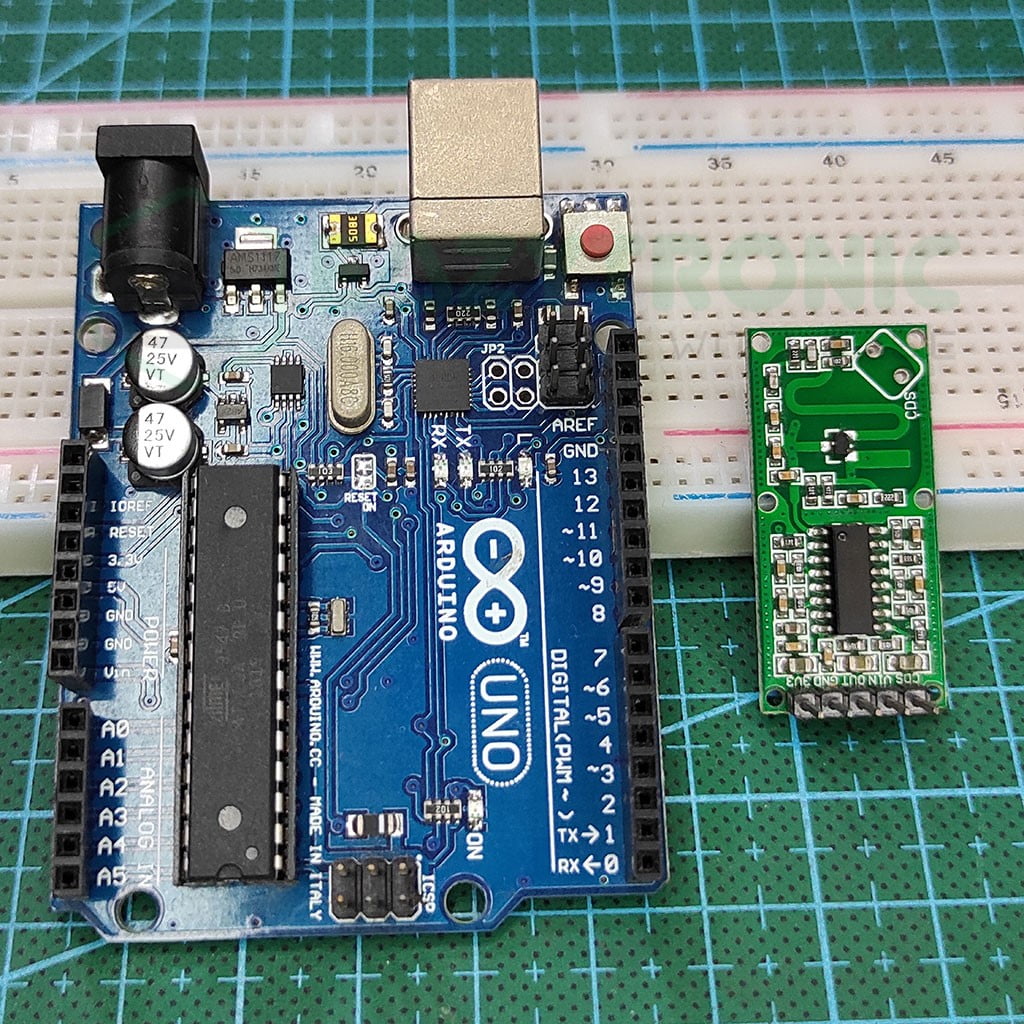
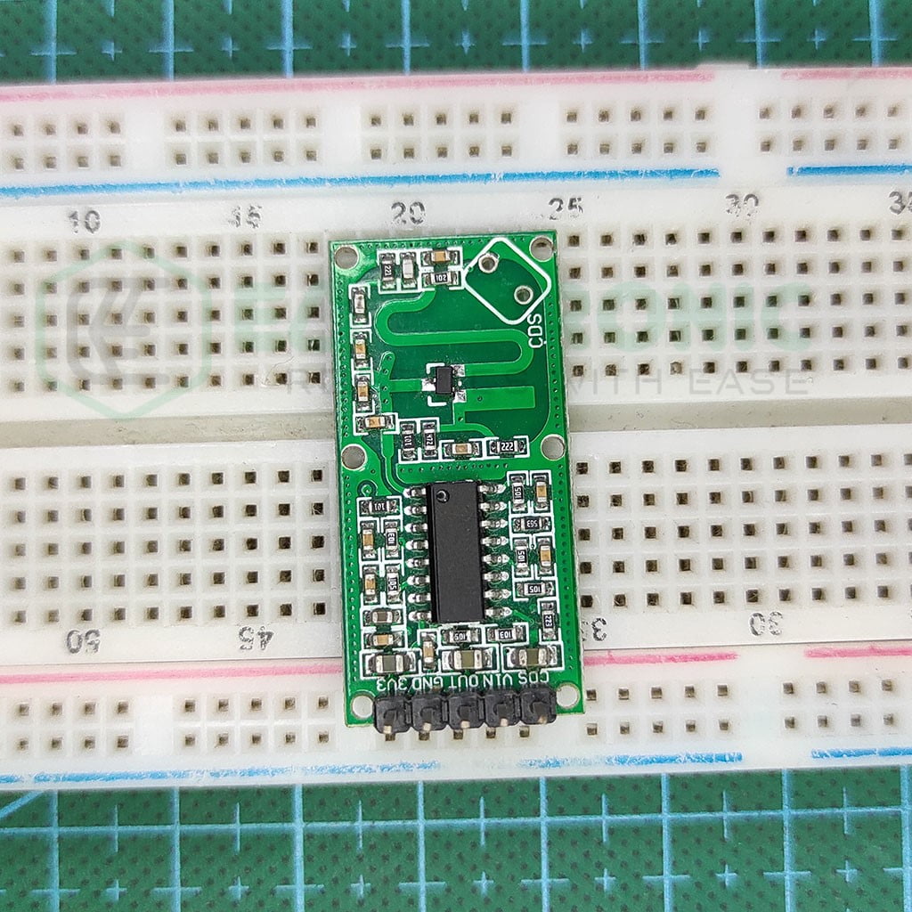
RCWL -0516
This sensor is commonly known by the name RCWL, but its complete name is RCWL-0516. This is long and confusing, like Ultrasonic and PIR sensors. However, you can easily get this in both online and offline markets for cheap with this name. However, there are many other versions of the sensor that I’d recommend for advanced projects Moreover, the sensor is small and can be placed anywhere, so there is no issue with placement.
Next comes to build quality and design, the sensor is designed on a rectangular PCB that contains mostly SMD components. However, we need to attach a few other components according to your needs. The components required can be easily found at any shop like a variable resistor, trimmer capacitor, and an LDR. But that depends on the task. You can read about this sensor in detail in a dedicated article on our website.
Although this sensor packs so many features, it occupies very little current. RCWL sensor works on the input voltage of range 4V-28V, with an operating current of about 3mA. The sensor shoots the microwave at a frequency of 3.18GHz, which is very fast, similar to your CPU operating speed. This gave a pulse time of 2s and a range of 7 m by default.
Lastly, it also comes with a board microwave antenna and an RF amplifier to boost the signal enough to reach the distance. These parameters can be controlled using several pads available on the sensor. This all is controlled by a single chip that is RCWL-9196. In combination with the MMBR941M RF Power Amplifier, it makes a perfect sensor for home security and automation.
Arduino UNO
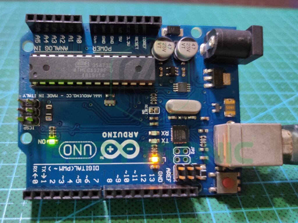
Arduino UNO is one of the most important boards I’d recommend starting with. This is not because it is easy, but the cost of this board is much less as compared to the other boards in the market. Moreover, the features it offers at such a price point are incomparable with any other board. Also, the board offers a great scope of repairability and durability, which is great to start with as you cannot invest much at the beginning of something.
The board is built on the ATMEGA328PU IC, which is the main controller of the Arduino UNO. ATMEGA328PU is an AVR-based 8-bit CMOS microcontroller that runs at a frequency of 16MHz. The main advantage of this microcontroller is that it comes with a DIP-28 package that is very easy to replace at the beginner level. Although this IC has versions in SMD, there are specific changes between those and the DIP version.
Along with this, the board packs within itself 2 KB of RAM that can run an ample amount of code required for most of the program. In combination with 32 KB of Flash memory, this board offers great specs for a beginner’s POV. Also, it comes with 1 KB of EEPROM Memory, which is very important in some codes that require storing the data even after the board resets.
Lastly, we’ll talk about the pins provided, and the power outputs available on the board. Arduino UNO comes with a total of 23 I/O pins that can be controlled via the code. This has 13 digital pins and 6 PWM pins, which is enough to practice with. Next comes the analog pin, which has 6 analog pins at 10-bit resolution. Also, it provides both 5V and 3.3V power lines for sensors and peripherals to attach.
Material Required
- Arduino UNO
- RCWL-0516 Microwave sensor
- Breadboard (Not recommended)
- Jumper wires
- A System to program Arduino
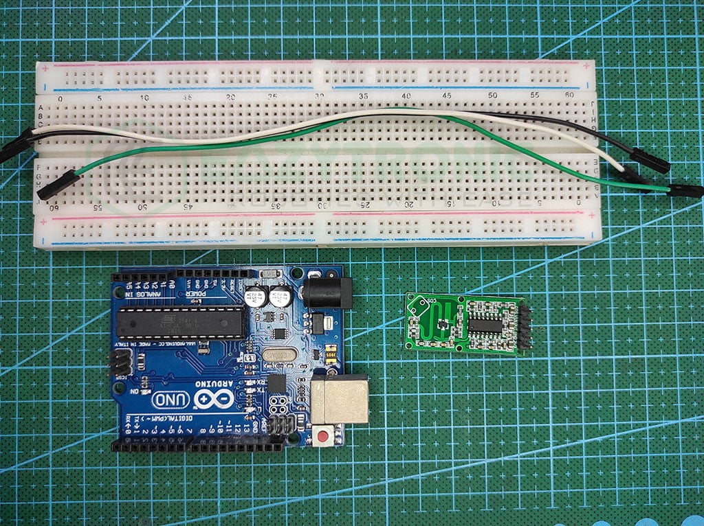
Fritzing Schematic
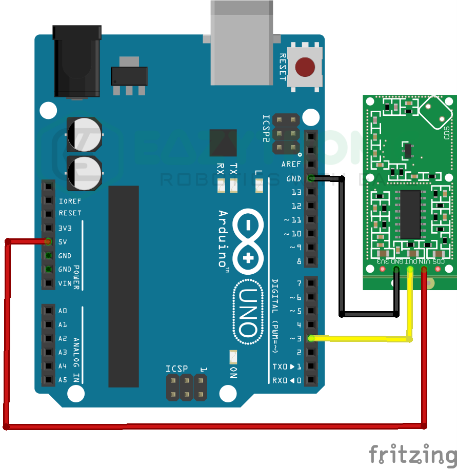
Wiring
| Arduino UNO | RCWL-0516 Sensor |
|---|---|
| 5V | VIN |
| GND | GND |
| D3 | OUT |
Programming Arduino
Once you have wired the RCWL with Arduino UNO, you can now proceed to program the board via the software. But before that, make sure to either download the latest version of Arduino UNO or update the software to the latest version. Also, make sure to install or update necessary libraries and board definitions in order to make sure that there are no compilation errors regarding this. To ease this step, I have already made a detailed tutorial article on setting up Arduino IDE and information about various Arduino boards.
Code
The code given below is for the RCWL Sensor with Arduino UNO, however, it can also work with other boards as it is very simple code. The sensor has not been modified so far, so all the parameters are default. If you want to change anything, make sure to adjust the code accordingly.
#define rcwl 3
#define led 13
void setup(){
  Serial.begin(9600);
  pinMode(rcwl, INPUT);
  pinMode(led, OUTPUT);
}

void loop(){
  if(digitalRead(rcwl)==HIGH){
    digitalWrite(led,HIGH);
    Serial.println("MOTION");
    Serial.println();
  }
  else {
  digitalWrite(led, LOW);
  }
}
The code is made simple to avoid any confusion, If you want to add more sensors or peripherals with the RCWL sensor, then make sure to change the code. The explanation for the code is given below, make sure to read it to make changes to the code. Also, make sure to save the code with some meaningful name in order to remember it. I have saved the code with “rcwl_with_arduino_uno.ino” no spaces are allowed in the name.
Explanation
Now comes the main part of the tutorial, the explanation. It is crucial to learn the workings of the sensor in order to write the code for the modified project that includes the peripherals that you attach.
#define rcwl 3
#define led 13
First, we start with defining pins for the RCWL-0516 Microwave sensor and LED. The LED used in this case is the onboard LED that can be controlled via pin 13. You can choose to change the LED but make sure to change the schematic and code accordingly.
The LED is used here to show the status of the RCWL Sensor, but you can use some other way for it, like using an LCD or OLED. To define the pins, I have used the define macro argument. You can also use the int type initialization for the pin.
void setup(){
  Serial.begin(9600);
  pinMode(rcwl, INPUT);
  pinMode(led, OUTPUT);
}
void setup()
Next, comes the setup section, Here we’ll define some statements that need to be defined once throughout the whole code. This section will only contain some beginning instructions and pin mode declaration. In the first line, we begin the serial communication between the board and the system to display messages on the system. This is purely optional, as we’re going to use let for that purpose also.
In the next two lines, we define the pin modes or pin types of the RCWL and LED. The RCWL sensor must be assigned input mode and LED to output. You can change the pins of both from the one defined as per your choice. But make sure to make changes in the code. Also, if you’re using any kind of display to demonstrate the status of the sensor, you need to add lines of code for that part.
void loop()
void loop(){
  if(digitalRead(rcwl)==HIGH){
    digitalWrite(led,HIGH);
    Serial.println("MOTION");
    Serial.println();
  }
  else {
  digitalWrite(led, LOW);
  }
}
The loop section is the final part. The most crucial part of the code, here the main part of the code, will be written. We start the loop with a condition to shorten the code and keep it simple. Also, I’ll be giving alternative lines of code for more understanding. You can replace these lines on your side for a much easier-to-explain code.
int val = digitalRead(rcwl);
if(val==HIGH){...............................
For the first line, you can replace the code with the lines of code in the above snippet. This will not change the functioning of the code, just create an extra variable for storing the value from the RCWL Sensor. The condition then checks for the value in the val variable and compares it to whether it is HIGH or LOW. You need to make sure that your Sensor sends the corresponding value to the condition, or else you need to switch the condition.
Next, we turn the LED (onboard) on pin 13 HIGH according to the condition if the sensor detects a motion. Also, simultaneously it prints “MOTION” on the Serial monitor in case you are not using LED. In the other part, we turn the LED off for all the other cases, as we don’t need an indicator for the idle state.
With this, we’re done with RCWL with Arduino UNO demonstration. If you need any help in using the sensor r with the code, let me know in the comment.