
Hey folks, today we’ll see IR Sensor with Arduino UNO. IR sensor is the simplest and might be the first sensor you’ve ever used in your first Arduino practical. Although this sensor is very simple and easy to use, it is used for small projects to big tech like smartphones also. Therefore, today we’re going to learn how to use this sensor with Arduino UNO. This sensor is very simple and can be used with any microcontroller in the same way. Moreover, there are different versions of IR Sensors available in the market. Let’s dig deeper into the section.
IR Sensor and Arduino in Brief
IR Sensor
This sensor is one of my favorite sensors, as I’ve also started learning about robotics from this sensor. IR sensor has no defined schematic or defined procedure. You just need to know some basic phenomena and traits of the components, and you can build this sensor on your own.
IR sensor works on the phenomena of reflection of light. Although the light used in this case is not visible to human eyes, it is present and does its job. InfraRed Sensor uses the InfraRed light that lies outside the visible spectrum of the human eye. You can find a detailed article on this here, where I have explained IR sensors in detail. For now, let’s revise the basics.
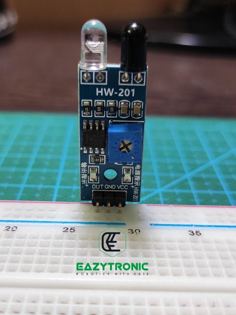
The sensor uses a pair of IR LED and a Photodiode to make all the magic happen. IR Led is a special type of LED that emits IR light, you can find these in Remote controls like cheap RC toys and TV. Along with this, it also uses a Low voltage dual comparator just like the sound sensor to produce the output signal.
Additionally, the sensor is capable of using any voltage that a common microcontroller operates on like 5V and 3.3V, so you don’t have to worry about the power issue. Also, the logic level of the sensors is based upon the power supply input, so make sure to power the sensor with a suitable power supply as that of the pin tolerance of the microcontroller.
Arduino UNO
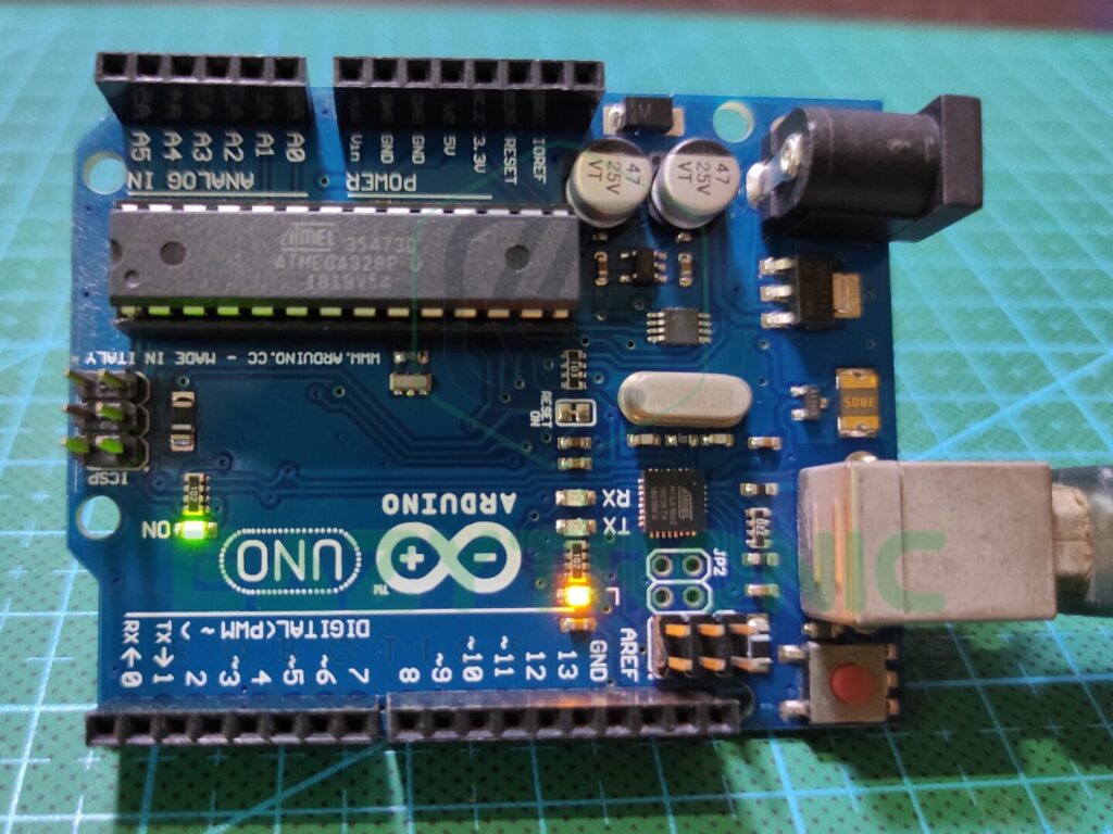
One of the simplest boards you can lay your hand on if you are going to start learning about ROBOTICS. Arduino UNO is the perfect choice for not only beginners but also for experimenters that require no use of a costly board. This is because the board is very easily available in the local and online market at an affordable rate. Moreover, it offers a high scope of repairability if something happens to the board.
Arduino UNO is built on the ATMEGA38Pu IC, which is an AVR-Based 8-bit CMOS microcontroller capable of running programs at 16MHZ. This microcontroller is available in the DIP-28 package that can be replaced easily, unlike other board that offers mostly SMD components. Other main components are also DIP that can be replaced. Also, the IC can be programmed using an FTDI programmer separately.
If we talk about performance and storage, rest assured it is capable of doing most of the projects without any issues. It comes with 2 KB of SRAM, which is paired with 32 KB of flash memory. This combination is quite sufficient for most of the projects. Moreover, it also comes with 1 KB of EEPROM memory that can store data permanently according to the user’s wish.
Lastly, let’s talk about the pins available and the power pins provided. Arduino UNO has a total of 23 i/O pins that constitute all the required pins. This includes 13 digital pins, within which there are 6 PWM pins. Moreover, there are 6 Analog pins that can operate at a 10-bit resolution. Along with a few other miscellaneous pins and both types of power output 5V, and 3.3V, it makes a complete package.
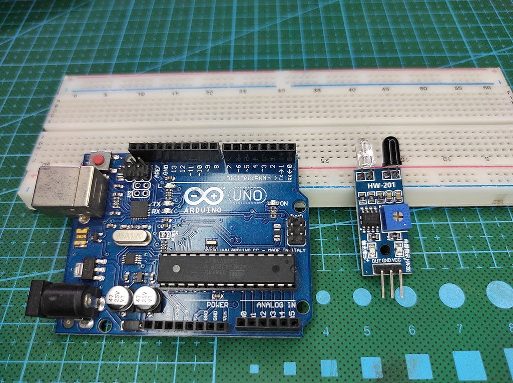
Material Required
- Arduino UNO
- IR Sensor
- Breadboard
- Jumper Wires
- A system to program Arduino
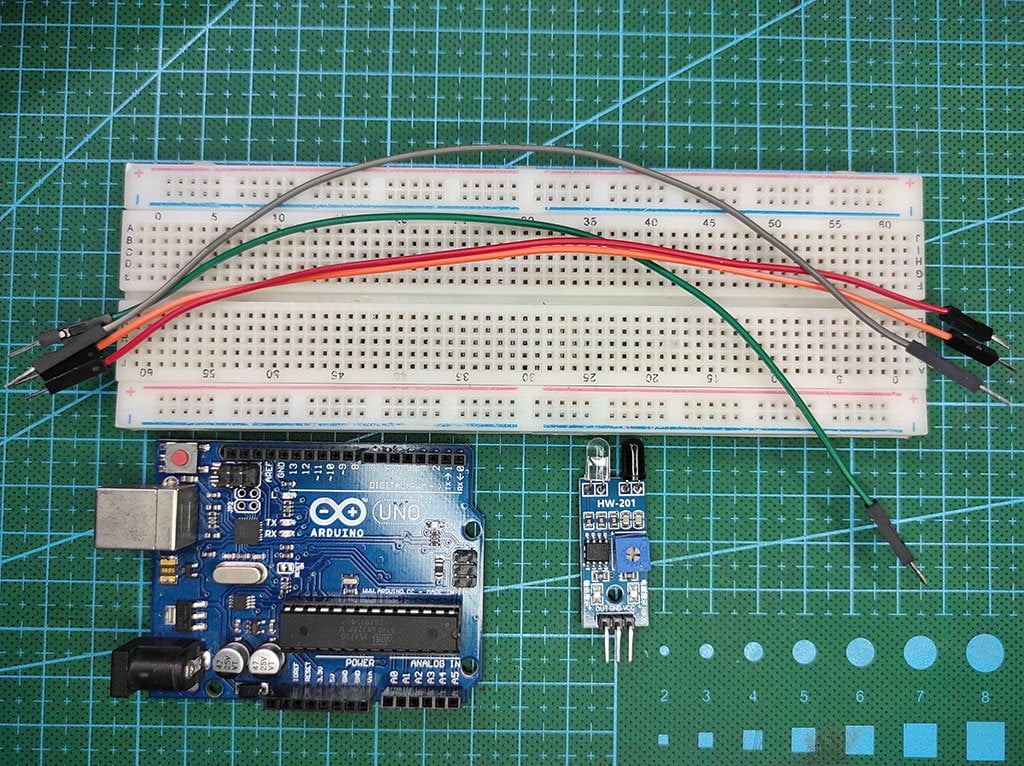
Fritzing Schematic
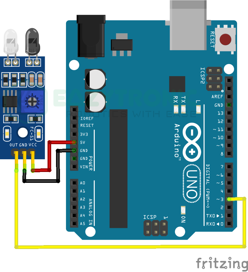
Wiring
| Arduino UNO | IR Sensor |
|---|---|
| 5V | Vcc |
| GND | GND |
| D3 | OUT |
Programming Arduino
Here comes, one of the important sections, here you need to prepare your system in order to program the Arduino UNO. If you have read other articles related to the Arduino series, then you might know what to do in this section. Then you can skip this step and proceed further to the next section. But for those who are new, they first need to download the Arduino IDE from the official website. Also, make sure to install all the board definitions and library needed to compile the program. If you want to know more about the Arduino IDE and its features, you can read its article form here.
Code
The code for this sense varies according to the model that you have with you. Like Tere are some versions that have reverse output. So it would help if you had t first confirm the model that you have. The one I have gives GND when an obstacle is detected, whereas n idle mode it gives a voltage signal less than 5V.
#define IR 3
#define LED 13

 void setup(){
   pinMode(IR, INPUT);
   pinMode(LED, OUTPUT);
 }

 void loop(){
   if(digitalRead(IR==LOW){
     digitalWrite(LED, HIGH);
   }
   else{
     digitalWrite(LED, LOW);
   }
 }
For the sensor that gives correct output like on detection HIGH whereas in idle state LOW signal needs some editing in the code that can be easily done. For this, makes sure to read the explanation section. Additionally, you need to save the code with the name “ir_sesnor_arduino.ino”, you can change the name so that it doesn’t contain any white spaces.
Explanation
Now, it’s time for the explanation of the code, for convenience I’ll divide the code into different sections so that you can scroll over to the corresponding one.
#define IR 3
#define LED 13
First, we start with defining pins for IR Sensor and LED, through which we’ll indicate the status of the IR Sensor. We’re currently using the Digital output f the IR sensor, therefore we’ll be utilizing a digital pin. Whereas for the LED we’ll be using the board LED provided.
However, you can change the pin to any you want, but for ease, I’ll e using the onboard LED. Instead of using an int variable to store the pins, I’ve used the, define macro argument, it has its own benefit that you’ll learn in the future.
void setup()
 void setup(){
   pinMode(IR, INPUT);
   pinMode(LED, OUTPUT);
 }
In the setup section, we must define the pin type we selected for IR Sensor and LED. Apart from this, we don’t need to start any communication as the suing the IR sensor doesn’t require. Also, the LED will be used to demonstrate the status of the IR Sensor.
In the first line, we define the pin mode of the Sensor pin as INPUT, this doesn’t change for either version. And for LED, we’ll be using the OUTPUT pin type. However, if you are using any display to show the output, you can include the lines required to begin such communication. I have already demonstrated the interfacing of different displays here.
void loop()
void loop(){
   if(digitalRead(IR==LOW){
     digitalWrite(LED, HIGH);
   }
   else{
     digitalWrite(LED, LOW);
   }
 }
Here, in the loop section, lies the main code. IR sensor is easy to use, therefore there’ll not be much code to write just to show the status of the IR Sensor. From the first line, we start by checking the condition of the IR Sensor. We check whether the output of the IR Sensor is HIGH or LOW. The output and the condition are totally dependent on the version of the IR Sensor.
Different models give different outputs on the detection of the obstacle. The one, I have, gives GND or 0V on detection. For the other version, you can refer to the next subsection. Manipulation of the code for the version will be explained there.
For this version, we check the condition and turn the LED on or off, contradictory to the IR Sensor output. You can also print this on a display for other tasks.
Alternate version
For the alternate version, the output is the same as the LED driving conditions. You just need to read the output signal. The loop section of the code given above should be replaced by the code given below. Also, you can change the code according to your wish if you are an experienced user.
void loop(){
   if(digitalRead(IR==HIGH){
     digitalWrite(LED, HIGH);
   }
   else{
     digitalWrite(LED, LOW);
   }
 }