

Hello learners, we’re back with another interesting article on Basic Electronics, and today we’ll be talking about IR sensors. IR sensor might be the first sensor most hobbyists must have started with, so let’s decode the mysteries of this sensor. Ir sensor is very simple to use, and its schematic is very easy to understand. Although this sensor seems to be easy, it is used in various places and applications and has a wide range of usage. Now let’s jump to the topic.
What is IR Sensor?
IR terms stand for Infrared, which refers to the spectrum of light that cannot be seen by the human eyes. Infrared Light is the term we might have heard in lower classes, but to understand this we need to have a look at the electromagnetic spectrum. This spectrum contains all the light waves along with their wavelength. In this, the Infrared Spectrum lies within 780 nm (1 nm=10-9 m) to 1 mm. The IR light spectrum is further divided into 3 types.
- NEAR IR :- 780 nm—1400 nm, fiber optic communication and medical field
- SHORT-WAVELENGTH IR :- 1400 nm—3000 nm, telecommunication and military purpose
- MEDIUM IR :- 3000 nm—8000 nm, chemical industry and astronomy
- LONG-WAVELENGTH IR :-8000 nm—15000 nm, Astronomical telescope and optical fiber communication
- FAR IR :- 15000 nm—1 mm, treatment of cancer
IR sensor also works like this, there are many other types which available in the market. These can be classified into Active Infrared Sensor & Passive Infrared Sensor. Passive infrared sensor so not need a radiation source artificially created for such purpose in their FOV (Field Of View). Moreover, they detect the energy or radiation emitted or reflected by object/obstacle in their FOV.
Passive Infrared Sensors are of two types, Thermal & Quantum. Thermal Infrared sensors are most common and are used very widely. IR Sensor, Flame Sensor, and MLX9061 are examples of Thermal Infrared sensors. These types of sensors are independent of the wavelength of the radiation, as they react to only thermal energy. Quantum ones are dependent on the wavelength of radiation and thus have better performance and detection than thermal ones.
Phenomena used in IR Sensors
Ir sensor works on various phenomena, but some of them are Planks Energy law, Black body radiation & Stephen law. These are important ones which state as follows. Energy radiated is directed proportionally to the wavelength. The Black Body Radiation curve for different wavelengths is inversely proportional to the temperature. The total energy radiated is directly proportional to the fourth power of absolute temperature. These are the statements of the laws stated above, respectively.
Advantages
- It is very easily available in the market and at very cheap. Also, you can build it if you want on a piece of perfboard is needed.
- Though this sensor is very basic, it is used in many projects and even in mobile phones for various actions.
- The sensor is highly repairable if something got damaged, it can easily be replaced.
Disadvantages
- The sensor needs to be kept some distance above the surface, or it may mess up the readings.
- The analog output is not that useful, as the sensor utilizes a comparator IC instead of an Op-Amp.
Price & Availability
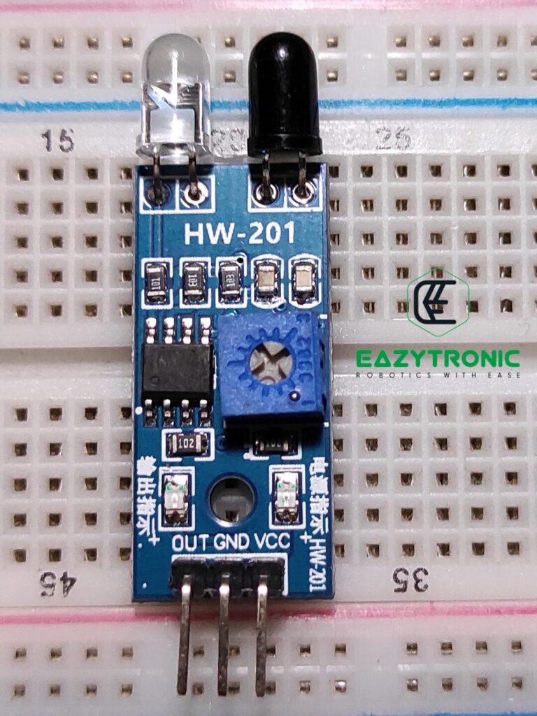
Pinout of IR Sensor
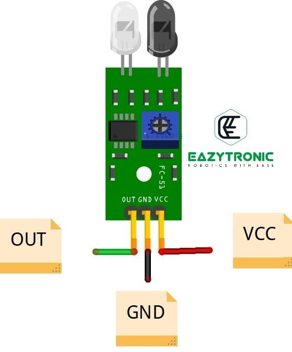
- Vcc:- this is the power delivery line, and must be connected to a higher potential or positive terminal of the circuit under prescribed limit
- GND :- This is the ground pin, must be connected to the lower potential or common ground of the circuit.
- OUT/D0 :- This is the output pin which gives the digital output (either 0 or 1). This pin gives the same output voltage as that of the input voltage.
- A0 :- This is Analog Output pin which is available only in some variants of infrared Sensor.
Specifications of IR Sensor
| Operating Voltage | 3.6V-5V |
| Current Consumption | 0.06mA |
| FOV/Measuring Angle | 35° |
| Detection Range | 2cm-15cm |
| Dimensions | 48cmx18cmx8cm |
Schematic
Here is the schematic of the IR sensor. This schematic is developed by reverse engineering an actual sensor, so authenticity can be given of the schematic. The schematic is very simple to understand and does not require costly components. You can also build the schematic on a piece of perfboard/ bare PCB. The main component of the sensor is LM393, which is a Low Voltage Dual Comparators. All the information related to LM393 is provided in the datasheet of the IC attached below.
LM393 is a Low voltage, Dual Comparators which compares the voltage on its first set of inputs. The inverting input pin is connected to the potentiometer with the power lines, which is used to trim the input voltage on that pin & hence the detection range. The Non-Inverting input of the comparator is connected to the photodiode, which is connected to the GND and pulled up to Vcc. The second comparator is not used in single output variants, but in dual output like D0 & A0 it is used to give analog output.
Working
Now let’s see the working of the IR Sensor, which is easy to understand, just you have to remember the working of the comparators. Working may be divided in parts for understanding purpose. Infrared sensor working completely depends on the main component of the sensor, i.e., LM393 IC. This is dual comparator which is not only found in this sensor but also in various other sensor. Due to its Low voltage sensitivity is widely used, but there is also other variant which uses LM358 as the heart of sensor. LM358 is Dual Op-Amp which boost the signal of the IR sensor to the acceptable limits.
The sensor is ineffective in bright light like sunlight, Fire, and black surfaces. As in sunlight and fire, IR radiations from various directions will enter into the FOV of the Photodiode. Similarly, in the case of a black (dark) surface, all the IR Light emitted by Ir Led will be absorbed, as a result, no light will enter the Photodiode. Hence, in both cases, the values will get messed up and result in the malfunction of the sensor.
IR LED/IR Transmitter
This is the another important component of the sensor, which emits or radiates the Infrared Light, which is further received by the Photodiode. If you take a look at the schematic, you’ll notice that the IR LED is connected to Vcc and ground with resistor in series. This is the simplest way to make an IR Led emits IR light, so we have used this. If you want to modulate the signal, then there are many projects based on microcontrollers to do so.
IR Light cannot be seen with human eyes but can be seen with the help of camera which does not have IR Filter. While most of the professional cameras come with it but still normal phone camera lack them, so it is the advantage if you want to see the IR Light. Apart from this, IR Led is also used in night vision CCTV cameras as they lack the same IR filter. So the camera sensor inside these capture the image in the IR Light which is quite bright in comparison with night vision mode in different cameras.
Photodiode
This is also the main component, or we can say that is the role-playing part of the whole sensor, without it the sensor is useless. The photodiode is not similar to other diodes available on the market, or if you don’t know what is a diode. Then refer to this. Photodiodes act as solar cells in the presence of IR light. They generate a very small amount of current which can be observed by using sensitive instruments. The current is very small that it can’t be detected by any microcontroller without amplification. Hence, this is the reason why some variants of the sensor have LM358 as the main IC.
IR Tester is very popular for testing the IR led and Ir remote, but the component which is used is Photodiode. Another such component that receives the IR signal like this is TSOP which is used in decoding the IR signals, which will be discussed in future posts. Photodiode becomes conductive in reverse bias to test them. You just have to connect an LED with a resistor to a battery and Photodiode in reverse bias with them. Now, if you point any sort of IR signal toward it, the LED connected will show blinking according to the IR signals.
LM358
This is the main component of the IR sensor, it does all the logical parts and gives out the output. This IC simply compares the voltage signal on its input, i.e., Inverting and Non-Inverting inputs. The output pin is connected to the D0 pin, which gives the digital output. This pin is also connected to the status LED, which is available on board to indicate whether the obstacle is in front of the sensor or not.
FAQ
Q. What type of output IR sensor gives?
The version of IR sensor demonstrated here only gives Digital Output, But there is another version which gives both Analog and Digital
Q. What is the output voltage range of IR Sensor?
The sensor can work between 3.6V—5V, you can also try it to use with 3.3V