
Hey Folks, welcome back, we’re back with another interesting article in Basic Electronics section. Today we’ll discuss about SOIL-MOISTURE SENSOR, this is another simple sensor from which a beginner can start with. Soil moisture sensor are very cheap and easily available in the market also comes in different variants which we’ll discuss further. Apart from this, you can also create this circuit on a piece of perfboard as it has very simple to understand schematic. So let’s begin today’s discussion.
What is Soil-Moisture Sensor?
Soil Moisture Sensor is another basic sensor that is very popular among beginners and hobbyists due to its low price and wide compatibility. This sensor measures the moisture in the moil and returns its value in digital and analog format. Soil moisture sensor comes in two parts which need to be connected to make them work. Although this sensor is quite effective, the area it covers for measuring the values is not adequate in comparison. You need to equip they are with numerous sensors for the data to be accurate and without latency.
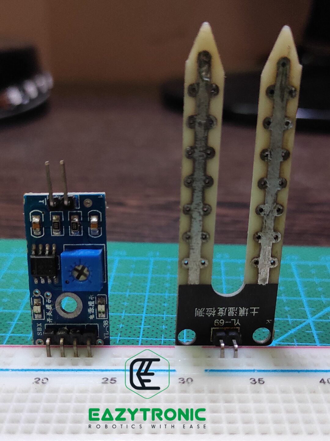
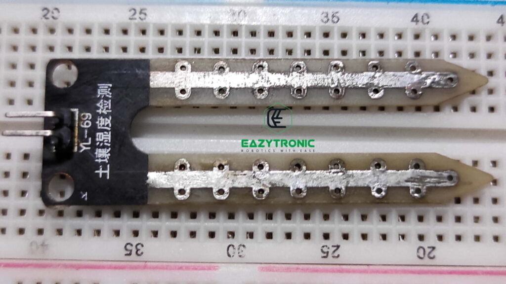
The Soil Moisture sensor which we’ll use to demonstrate today is resistance based. In simple words, can say that it depends on the transfer of electric current through the soil between the probes. The probes which are provided with the sensor are not of good quality. Hence, it is advised to use them with care or made custom ones for a specific purpose. Disregarding all, it gives an analog value that is far more usable and accurate than the digital value, i.e., 0 & 1.
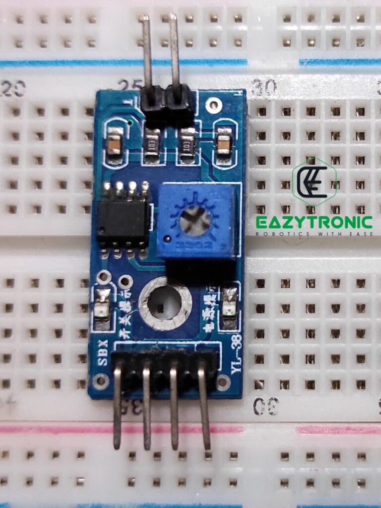
This sensor is similar to the IR sensor and various sensors, which uses the same IC as the main chip. Along with the main chip, it also has a similar feature like for trimming the values delivered to the microcontroller via potentiometer. The probes mentioned earlier need to be sanded and wiped regularly, as they deposit a layer of salt upon them after some time. Also, rusting of contact pins between the main board and probes can lead to wrong values from the sensor.
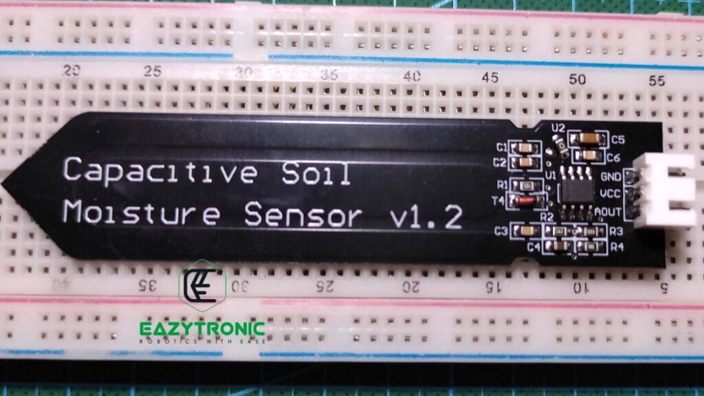
There is another version of this sensor available that also is widely used, i.e., the Capacitive Soil Moisture sensor. The working of the sensor is somewhat similar, along with the construction, but I haven’t used that so can’t say anything confidently. This version only gives analog output, which is acceptable as we can use the analog output ad digital with the help of mapping (Arduino) or similar functions.
Advantages
- This sensor is cheap and easily available in the market, hence it is among the basic sensor with which you can start.
- Interfacing of the sensor is very easy for almost all microcontrollers as the input voltage is within range of almost all microcontrollers available in the market
- It is easily repairable and also can be built on custom PCB for specific use.
Disadvantages
- The probes provided with the sensor are not of good quality, prone to corrosion.
- The wires connecting the main board and probes PCB are of low quality and get corroded after some time.
Price & Availability
PinOut Soil Moisture sensor
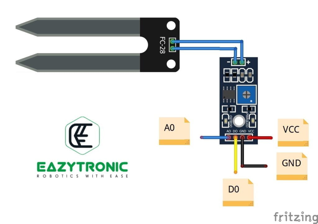
- Vcc:- This is the power delivery line that must be connected to the higher potential under directed range. It is recommended to connect it to the microcontroller power delivering pin.
- GND:- This is the lower potential pin that must be connected to the common ground of the whole system.
- A0:- This is the output pin which gives analog output within the reference voltage or input voltage range.
- D0:- This is the output pin for the digital output, which gives either 0 or 1 as output. The high voltage potential is the same as the input voltage.
| Operating voltage | 3.3V—5V |
| Main board dimension | 3 cm x 1.5 cm |
| Probes dimension | 6 cm x 3 cm |
| Output type | both Analog and Digital |
Schematic
Above is the schematic of the Soil-Moisture sensor, we have created this sensor by reverse engineering an actual sensor. Hence, you can use this sensor to create the sensor on a custom piece or perfboard or PCB. In this schematic, the main component of the sensor or the IC which is used is LM393. In this schematic also LM393 is taken as the main active component. It is a Low-Offset Voltage, Dual Comparators, like in the IR Sensor schematic here also it is used to compare the voltages on both inputs.
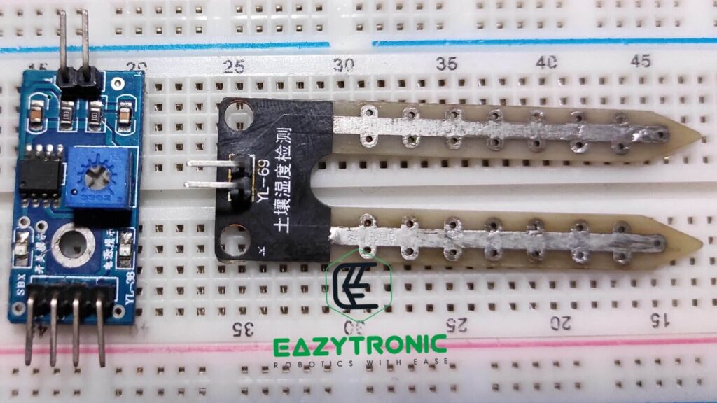
A PCB along with the main board is also included in the package, this is the probe PCB and is used to gather the moisture data from the soil. Although these are the provided set of probes, according to my experience these are not of that good quality. There will be deposition of a layer of salt over them after some time, which needs to be cleared or sanded. If this deposition of salt continues, the pin headers may also get rusted, resulting in overall damage to the probes. Hence, I advise you to either use a high-quality probe or use a custom one. For some DIY solutions, you can tin the conductive part of the probes so that they’ll not be affected so easily.
Moreover, you have to make sure that the wires connecting the main board and the probes are not worn out. Instead, use some nice quality wires, as those wires can also result in the wrong transmission of values. The values from the analog output of the sensor can have some noise. This can remove either by trimming the potentiometer or using software mapping functions.
Working
Now let’s have a look at the working of the Soil moisture sensor. It is somehow similar to the IR sensor but differs in some minor things which we’ll discuss here. As always, the main chip or main component is LM393, it is a Low-Offset Voltage, Dual Comparator. The job of this IC is to compare the voltage on its both inputs, i.e., Inverting and Non-Inverting input. Here also, the inverting input is connected to the potentiometer with power lines to give the reference voltage for the comparison. While the Non-Inverting input is connected to the probes, which is connected to GND and pulled up to Vcc. Datasheet for LM393 is attached below.
The output pin of the comparator is connected to the digital output of the sensor, with being pulled up to Vcc. Also, the onboard status LED is also connected to the same pin for indicating whether there is moisture in the soil or not. Further, the analog output of the sensor is connected to the Non-Inverting pin of the comparator, which means it gives the direct values from the probes. Therefore, I have advised to use better quality wires for connecting main board and the probes.
Lastly, some important tips for efficient use of the sensor. While you are using the sensor, actually measure the amount of potential transferred between the probes. This depends upon the number of free ions in the soil for the conduction of electric charge. If you add fertilizers into the soil then the values of the sensor can be manipulated which is not right. This is experimented with by me, and I was able to manipulate the value of the sensor just by adding some salt to the soil.
With this we end our detailed explanation about soil moisture sensors, I hope you like it. If you need any more help regarding this, then comment down below.
FAQ
Q. What is the input voltage range of the soil moisture sensor?
The soil moisture sensor can be powered within the 3.3V-5V range.
Q. What is the output voltage range of the sensor?
The output voltage for the both digital and analog output is under the input voltages.