
Hello Folks, we’re back with another article in the Basic Electronics section. Today we’ll discuss PIR Sensor also known as the PIR Motion sensor. PIR sensors are easy-to-use sensors that can be used by beginners to learn and strengthen their hands in the field of electronics. These sensors are easily available and are similar to IR sensors, so you don’t feel much different, but keeping that all aside I’ll explain every part in complete detail, so let’s begin.
What is PIR Sensor?
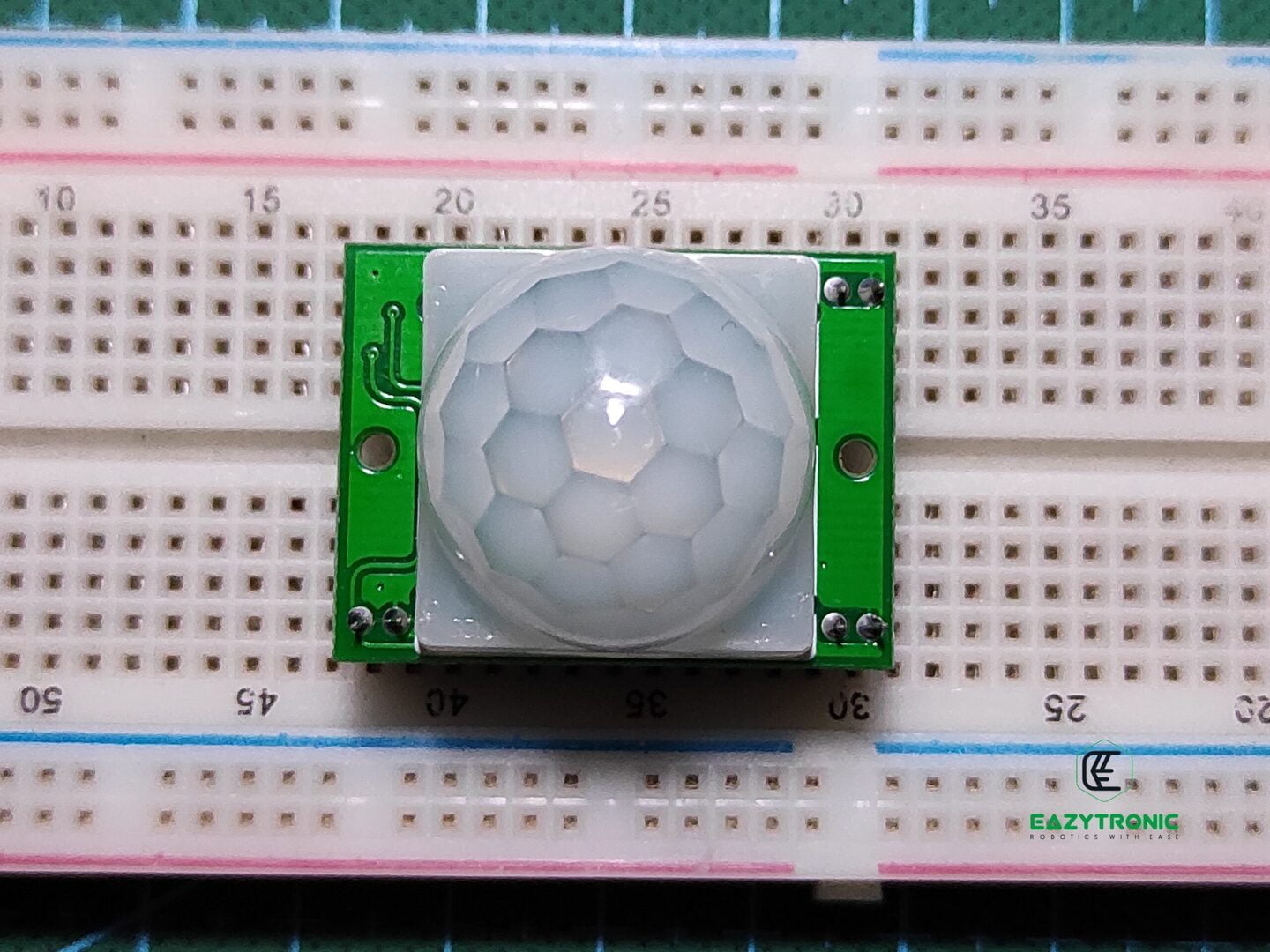
PIR sensor also as Passive Infrared Sensor, resembles/adapt its name from the Infrared sensor as working of the sensor is somewhat similar to it. This also works on the principal of reception of Infrared light, but in all it detects the light coming from the objects nearby it within a specific range. It has more range that the IR Sensor on comparing with it. Moreover, it has more field of view/Measuring angle than that of Infrared Sensor, This also due to the attachment made to be place in front of the actual sensor i.e., the white color semicircular thing.
HC-SR501 is the module uncommon name that is also used, but commonly it is known as PIR Sensor. HC-SR501 is neither very complex to use nor easy, it only requires some of the basic information which needs to be kept in mind while operating it. Passive Infrared Sensor this term defines much about the sensor, unlike the IR sensor it doesn’t generate the IR light but more likely lies flame sensor which detects the IR Radiations coming from the fire. The principle of thermodynamics states that any object either living or non-living above the Absolute Zero temperature i.e., −273.15 °C emits some amount of IR Radiation that depends on their body temperature.
These Radiations are not normally visible to human eyes as it doesn’t fall under the visible spectrum of light, so we need certain special devices to see these radiations. PIR Sensor detects these radiations and on the continuous data and movement or change of the path of Ray of Infrared Radiation, it detects the movement. This seems to be a bit confusing, so for example, consider a case. Suppose you are holding a laser pointer in your hand standing still but after some time you start moving so does the light ray of the laser pointer, so it changes its vector path.
This path change results in a change of intensity of Infrared Radiation falling on the PIR sensor, thus it detects that something around it is moving. More detail will be discussed when we see the schematic of the sensor. With the schematic, I’ll explain the role of each component in the working of the sensor.
Advantages
- The main advantage of this sensor is that it is cheap and affordable and easy to use. It is easily available, and beginner-friendly.
- The output is simple and the sensitivity and delay can be adjusted by the potentiometers. The components are replaceable except the SMD passive components.
Disadvantages
- The sensor seems to be quite strong and durable, but the Fresnel lens seems to be a bit light and prone to damage.
- The sensor has a default delay time of 3s which is quite trouble some as you have to hit and try the time delay thing.
- Though sensor is sturdy, but it lacks perfect mounting holes placement and needs to be checked fo LDR before using it in bright light.
Price and Availability
Pin Out of PIR Sensor
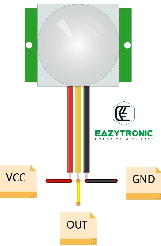
- Vcc :- This is the power delivery line or the high potential point, which can be powered up to 5 volts.
- GND :- This is the ground potential and must be connected to the common ground of the hole system
- OUT :- This pin gives the output of the sensor, which is HIGH on detection of moving object and GND in idle state
Specifications of PIR Sensor
| Operating Voltage | 4.5V—12 V |
| Current Consumption | 60 mA – 65 mA |
| Field of View/Measuring angle | 120 °C (approx.) |
| Measuring Distance Range | 7 meters |
| Output | TTL Output @ 3.3V Logic Level |
| Temperature Range | -20 °C—80 °C |
| Delay time Range | 5s—200s |
| Dimensions | 32mm x 24mm x 18 mm |
Schematic
The given above schematic is for the HC-SR501 PIR Sensor, which is designed by me based on the information on the internet. This is for understanding repairing purpose only and not advised to implicate into sensor for custom uses before verifying with the actual sensor. Sensor is built out of components which can be easily found on online and offline stores. The main components are BISS0001 IC and D204B Pyroelectric Sensor.
As stated earlier, PIR stands for Passive Infrared Sensor, but its complete name is Pyroelectric Infrared Radial Sensor. The Pyroelectric term defines an object that detects heat (Infrared Radiation) and transforms it into an electric signal. The actual sensor is inside a metal casing that contains two pyroelectric sensors in series. This sensor is a circuit that converts Infrared Radiation into electric signals. The internal schematic of the metal sensor is given below, have a look.


This metal sensor is covered with a white hemispherical or dome type structure which act as Fresnel lens. This lens does a crucial role in working of the sensor and collecting the Infrared Radiation in the surroundings. Along with these, many passive components also contribute in the complete working of the sensor. The sensor is provided with a potentiometer for adjusting the range and delay of the sensor. Also, it is provided with mode selection jumper which plays different role in each mode.
Working of PIR Sensor | HC-SR501
Now let’s discuss in detail about the working of the PIR Sensor or HC-SR501. Its working is divided into further sections:
D204B Pyroelectric Sensor
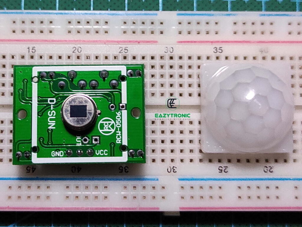
This is a hermetically sealed metal housing that contains the main component of the hole sensor. This sensor contains two Pyroelectric sensors in series and some other components. The opening or window is covered with IR-transmissive material, typically silicon, to allow IR Radiation to enter the sensor. It contains a JFET that gives a high impedance signal which is delivered to BISS0001 IC, PIR controller chip. This sensor is covered by a Fresnel lens which concentrate all the IR Radiation on the window which allow the radiations to pass.
Overall Sensor
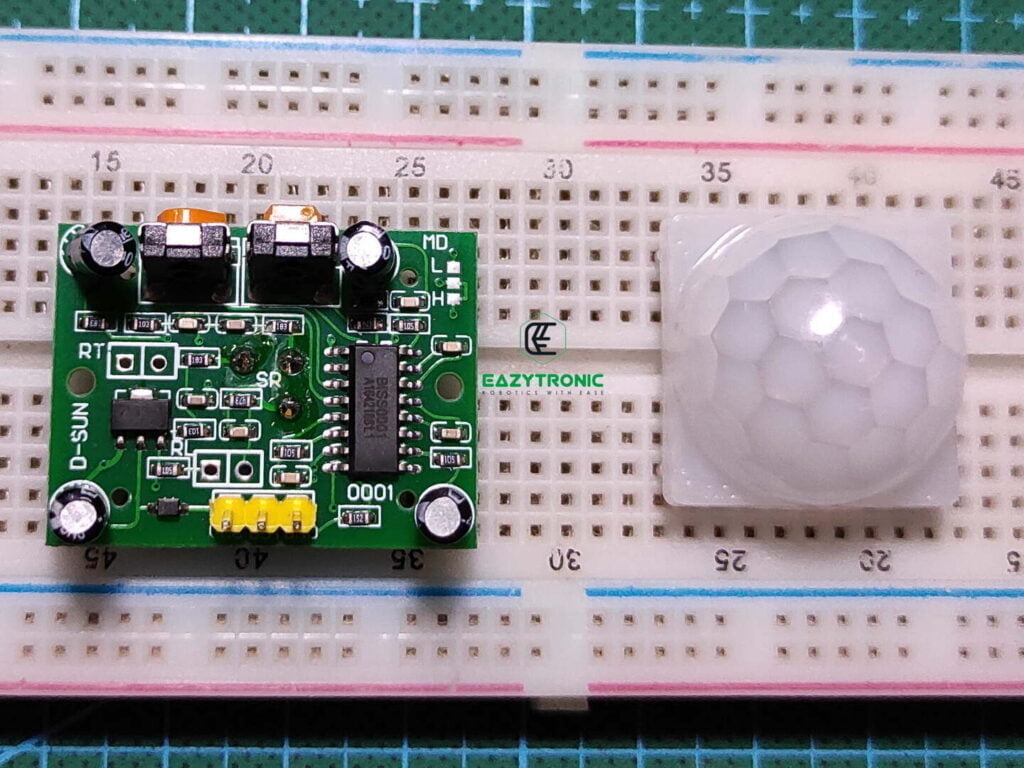
Complete sensor is built out of BISS0001 IC which is PIR controller IC, datasheet for it provided above. This sensor identifies the change in the peak voltage signals coming from the Pyroelectric sensor and gives it’s output. When the sensor is Idle, or we can say when there is no movement in its surroundings, it has some fixed voltage. When there is movement in front of the sensor, the peak voltage fluctuates to HIGH and low for the two pyroelectric sensors, respectively.
The signal at the output of the sensor can be adjusted along with this, duration of individual & delay between the two consecutive signals with the help of potentiometers provided o the board. Output is of TTL type with the reference voltage of 3.3 V Logic. This voltage is the same as the pyroelectric sensor reference voltage, i.e., idle state voltage for the pyroelectric sensor. The fluctuation of peaks of voltages from the pyroelectric sensor is read by the controller IC. Further, output signal is normalized into a constant signal for the Output.
Modes
There are two modes in which this sensor can be configured to be used. Modes are mentioned and explained below with examples:
Non-Repeatable Trigger
In this type of trigger, the sensor responds to the first detection irrespective of whether the subject has left the FOV or not. For example, if a person enters the FOV and then stays there. If the sensor is configured in this mode, the sensor will give high output once and then give low output. If the subject then moves after it in the FOV then the sensor again will give the HIGH output and the process continues.
Repeatable Trigger
In this mode, the output remains high until the subject leaves FOV. After that, timing starts when the subject leaves FOV and turns the output to LOW. For example, if a person enters the FOV of the sensor and stays there. The output of the sensor will remain high until the person leaves. Once the person leaves, it starts the delay timer and switches the output to low.
Note:- If you are using the PIR sensor in bright light or sunlight, you have to check whether LDR is connected. It should be connected, or the value will be wrong and shows an error.
With this we come to an end of this detailed article. I hope you like it and if you want any more information let me know in the comment.
FAQ
Q. What is the logic level of the PIR Sensor / HC-SR501?
The sensor works on the 3.3V logic level, but it doesn’t affect its performance as the output is quite stable for high logic level devices.
Q. Can the sensor still be used if the Fresnel lens is missing or using only a pyroelectric sensor?
Yes, you can, but the performance of the sensor will be affected as the IR Radiation rays can now no more be concentrated on the pyroelectric sensor which may affect the overall performance of the sensor.