
Hey Guys, Welcome back, we today are going to start a new section that is Arduino and mainly ARDUINO IDE. Arduino IDE is the main software that is used for programming for almost all of the microcontrollers available on the market. This IDE is very easy to program as it uses basic C language also it has support for almost all boards. This makes it ideal for every programmer to use it and make interesting projects. Now let’s begin its description.
What is Arduino?
Arduino is the name that has become very popular since its origin in 2005 which was to make a tool for the interaction of students in Italy. Since then this has become a chain of a wide range of boards for all purposes and needs and does its job as good as ever. Arduino is an Open-Source organization that has the best support in today’s world for beginners and experienced users. Apart from this, it also provides all the required documents for making custom board designs. This is a great source for practicing and pursuing this as your hobby or profession.
These boards come in various versions, types, and series and all of them are open sources. Moreover, it provides a great and very simple platform to interact with electronics, from blinking a simple LED to complex projects. All of this can be done with just some lines of code, and writing them requires some basic learning. Further, it comes with plug and lay USB connection with any device for programming development boards. One of the most popular and common Boards which is used is Arduino UNO. This is something every hobbyist starts with and tries all experimenting with this before any professional one.
Arduino Boards
Now let’s see some of the common boards which are used by almost all people and are therefore popular.
Arduino UNO
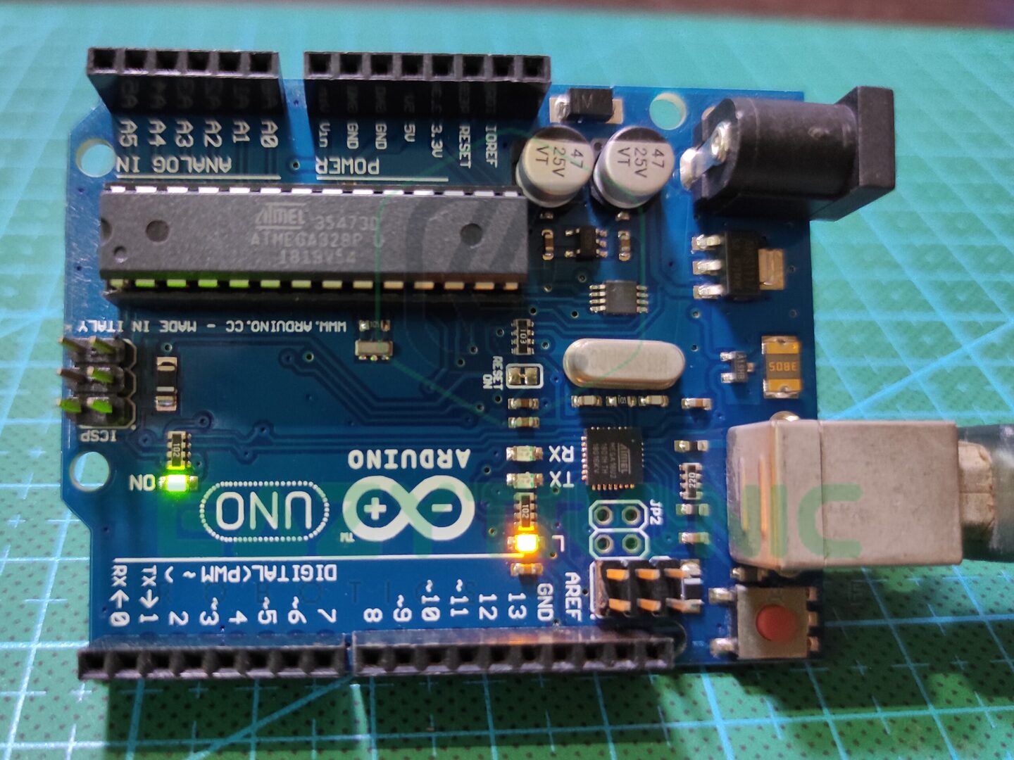
This is the most common board which you’ll be using in your entire path of electronics. This is the best board for beginners and hobbyists who are going to start learning Arduino. Among all the Arduino boards, this holds about half of the purchase and popularity. Furthermore, it is replaceable and repairable to some point, unlike more advanced ones. Arduino UNO comes in two versions, one is with THT main IC and the other is with SMD main IC. Because of the replaceable THT IC, it is recommended to use the THT one. All the other components are SMD, not the connectors, or power input jack.
Above is the schematic of the Arduino UNO board, this can be easily downloaded from the official website. Along with this, PCB files can also be downloaded from the same place. The files can be easily opened in Eagle Designer, or you can import them in Altium designer for more flexibility. Now let’s have deep learning about the design and various sections of the Arduino UNO.
Main Chip
ATMEGA328P is the main chip, and around this complete board is constructed. This main chip comes in various packages which can be used according to the need, but in this version, the THT or DIP package of the IC is used. This IC seems to be a bit small but holds wide capabilities within it. Some of Its features are mentioned below.
| Package Type | SDIP-28 |
| Operating Voltage | 1.8V-5.5V |
| Architecture | CMOS 8-bit based AVR |
| Working frequency | 16Mz |
| Programmable Pins | 23 |
| ADC Resolution | 10-Bit |
Power & Pins
The Arduino UNO has 14 digital Pins numbered from 0-13, out of these, 6 are PWM pins that can be used to generate PWM signals. Moreover, Pin 5 & 6 off Arduino is capable of producing PWM Signals at 950MHz. The PWM pins are marked with the ~ symbol before the PIN. Along with this, it also has 6 Analog pins with ADC Resolution of 10-bit, i.e., 0-1024 data points. It has 2 KB of SRAM and 32 KB of programmable flash memory also it has EEPROM memory of 1 KB. Apart from all this, the Board also has a power indicator LED, and a Built-in LED at pin 13 which is connected via op-amp.
Now let’s shift to the function of various pins. Firstly, Pin 0 & 1, these pins are used for Serial Communication and used for programming the microcontroller. Also, these pins can be programmed using any normal pins but must not be connected to any device during uploading the code to the boards. It also has SPI & I2C communication which are on pins (13,12,11,10) & (A4,A5) respectively. For supplying the power to the power jack is available which can be used to power the board from 5V12V.
Furthermore, onboard voltage regulators for 5V & 3.3V are provided, which can be used to provide power from the power rails available on the left side of the board. Vin pins on this side can be used to power the board the same as the power jack, but the wires should be thick. Lastly, the board can also be powered via the programming USB type B port.
Other boards
Arduino Nano
| Main chip | ATMEGA328P-AU |
| Operating Voltage | 5V |
| Input Voltage | 7V-12V |
| Working Frequency/Clock Speed | 16MHz |
| Architecture | 8-bit AVR |
| Digital Pins | 22 |
| PWM Pins | 6 |
| Analog Pins | 8(A0-A7) |
| Communications | SPI, I2C, UART |
| Flash storage | 32 KB |
| SRAM | 2 KB |
| EEPROM | 1 KB |
Arduino MEGA
| Main chip | ATMEGA2560 |
| Operating Voltage | 5V |
| Input Voltage | 7V-12V(20V max limit0 |
| Working Frequency/Clock Speed | 16MHz |
| Architecture | 8-bit AVR |
| Digital Pins | 54 |
| PWM Pins | 15 |
| Analog Pins | 16(A0-A15) |
| Communications | SPI, I2C, UART |
| Flash storage | 256 KB |
| SRAM | 8 KB |
| EEPROM | 4 KB |
Installing Arduino IDE
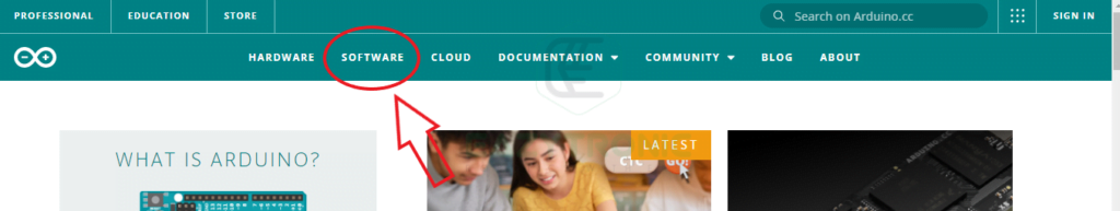
Firstly, go to the official Arduino website, and visit the software section on it. For this, click on SOFTWARE appearing on the header of the webpage.
Now scroll down, and you’ll see two versions that can be downloaded. First on is the conventional one which is used all these years. The other one is the future version which is the RC version based on VS Code and in my opinion very helpful.
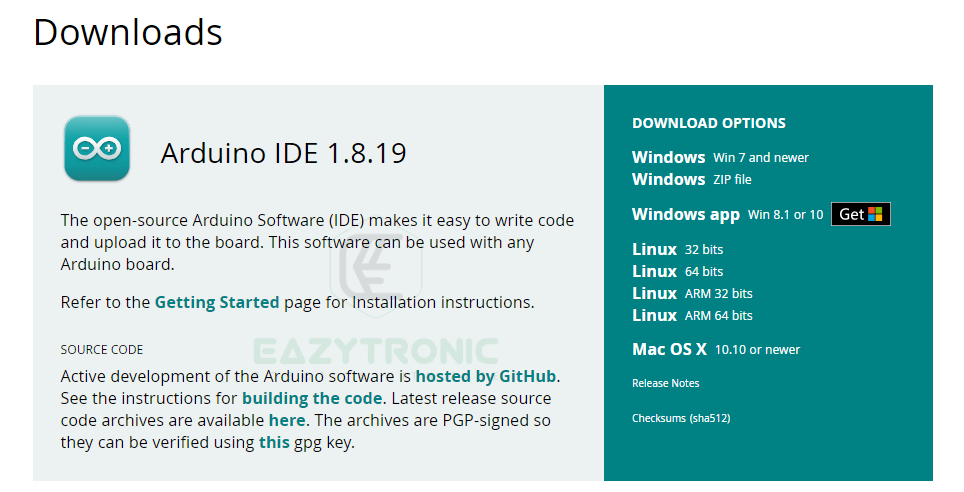
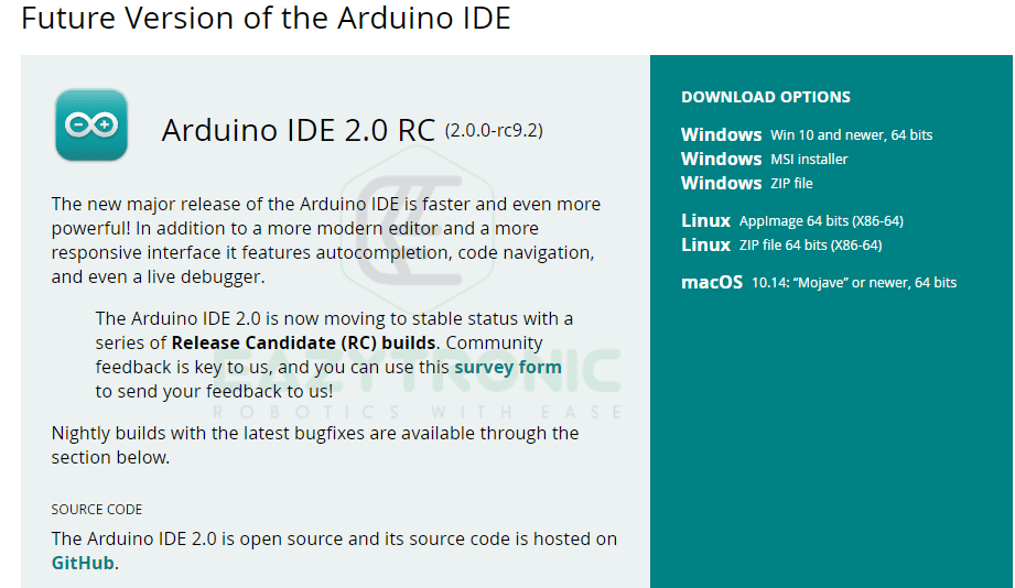
Now download either one of them according to your choice. I have downloaded both and so recommend them to you because both are useful in their unique ways.
After that install them, one piece of advice, try not to include any space in the folder destination because sometimes it may cause an error. Furthermore, also make sure that you have installed them for all users and by admin rights, as sometimes it shows an error in some storage permissions. For this, make sure that the above conditions are met. Once you have installed now half of the work is done. Now you only have to install libraries and boards and also add additional boards for support.
First Time Opening
If you open the software for the first time, the screen would appear like this, with a default sketch of code. This section contains the setup() section and loop() section, both of which have specific purposes. If you have studied some C/C++ language, then you may relate to it. In addition to this, you can add more lines and complex code according to your need, and the same for me in my future posts. But today we’ll see a simple code in this IDE and Arduino UNO. But before this is, let’s see some basic checks which you should do before the connecting board and uploading code.
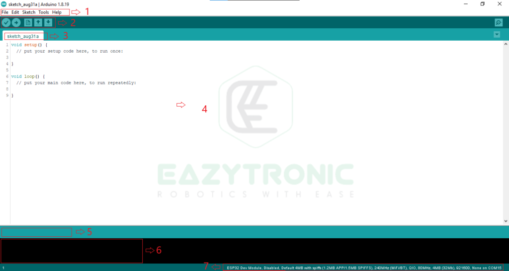
| 1 | Menu Bar |
| 2 | Quick Actions Button |
| 3 | Tabs in current folder |
| 4 | Editor |
| 5 | Status Bar |
| 6 | Console window |
| 7 | Board Information |
While installation there must be some pop-ups for driver installation, these are for the official Arduino drivers which are used to detect the type of board you are using. But on the other hand, there are also such boards that are clones and cheap. These boards sometimes use a cheap serial USB to UART/Serial communication IC, such as CH340. There are separate drivers for these boards, which are included below. So download these drivers also and install them for future use. CH340 Drivers.
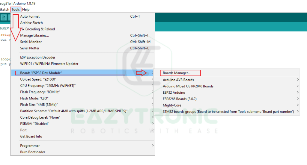
After this, check for Boards Update in Boards Manager and Libraries Update in Libraries Manager. This is essential as before writing code you must update all libraries and board definitions to the latest version to avoid any error.
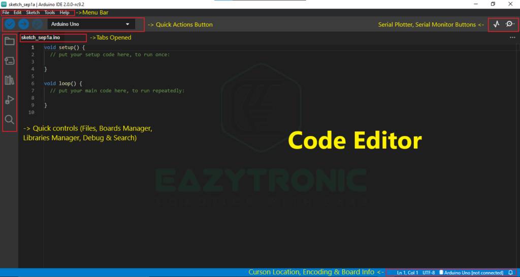
Arduino IDE 2.0
Although all the appearance is somewhat similar to the old version, I’ll give you a brief introduction.
Blink LED | First Code in Arduino IDE
Well now we have come to almost the last section of this Arduino Intro Article, so just sit back and enjoy this. This Blink Led sketch is the same for all Arduino Boards and the variable used, automatically selects the PIN according to the board used. Moreover, you can change the values like PIN and others, but you can’t save the changes as this is a non-editable file, so you have to save a fresh copy of it.
Material Required
- An Arduino UNO (or any other Board)
- Programming cable
- Device with Software Installed
Code
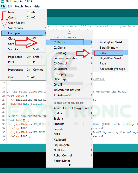
Now open Examples OF Blink LED as shown below. After this, you can change the PIN and delay time accordingly.
In the code, you’ll see two important sections, which are void setup() & void loop(). These two are common sections that need to be there in any code for the code to compile, else the code will not compile. Now heading to the main code, it contains some unfamiliar terms for beginners and is somewhat familiar for people with C/C++ language background.

void setup()
In void setup() you’ll see these lines of code
void setup() {
  pinMode(LED_BUILTIN, OUTPUT);
}
This line pinMode(), it is used to assign the pin type to the pin. Pin can be assigned as INPUT, OUTPUT, INPUT_PULLUP, that depends upon your requirement. Also, various other important lines which needs to be imported once in the whole code. Moreover, there is also initialization of variable which is done above all the sections else like any other language variable will become local to that section.
void loop()
void loop() {
  digitalWrite(LED_BUILTIN, HIGH);   // turn the LED on (HIGH is the voltage level)
  delay(1000);                       // wait for a second
  digitalWrite(LED_BUILTIN, LOW);    // turn the LED off by making the voltage LOW
  delay(1000);                       // wait for a second
}
In the loop section, there is all the main code that needs to be recursive. Moreover, you can also add functional calls, i.e., can be called inside the loop section. Now let’s see what is inside the loop section of the blink LED. In this section we see the first line i.e., digitalWrite(), this function writes data to the pin. Moreover, this function also has a similar one, i.e., analogWrite(). After this, we see the delay() function, this function takes values that correspond to the milliseconds. In addition to this, there is also a function that takes microseconds, but it is not useful here, so we use this one.
In digitalWrite() function we see two parameters, if you didn’t understand the parameter then I highly recommend you learn any programming first or get a basic idea of them, before proceeding. The two parameters are the PIN and the other one is the state of the pin. The state of the pin can be HIGH, LOW, and PWM values, but here we only need to make a LED blink, so we use HIGH and LOW values.
Uploading the Code in Arduino IDE
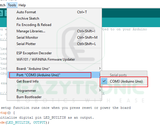
For uploading the code, you first need to select the board type which you are using. You can easily do this by going under the Tools menu, then Boards. If you have installed more than one board support then select the correct one like in my case Arduino AVR Boards. After this from the wide range of boards select the one you have or are using.

After this, select the port to which your board is connected. Make sure you select the correct port, or the device which is connected to the selected one may damage.
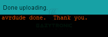
Now the final move is to upload the code for this, click on the upload button on the quick action toolbar.

Now wait for the uploading process to be, and it would appear like this.

With this, we sum up our intro article on Arduino IDE along with Blink LED. I hope you like it, for any other suggestions, comment down below.