
Hey learners, welcome, today we’ll start the intro of ESP8266 (NodeMCU) Boards. These boards are quite popular due to their IoT and other features. Along with this, these can also be programmed using the Arduino IDE. We recently completed an article on the introduction of Arduino IDE and Setting It up, have a look at it for more information. Now let’s head to the main tic and start the ESP8266 section.
What is ESP8266
You might be wondering what are these boards and how can we use them, So in simple words, these boards proved to be the revolution in the IoT field. Most of the devices we use in our day-to-day life are based on IoT, which means they can be controlled and operated over the internet. This revolution of technology demanded a solution to high-cost chips and development boards. Thus, A Shanghai based company Espressif Systems developed these boards which are quite affordable at a cheap price. There are many versions of these boards, ranging from ESP8266-01 to ESP8266-12.
ESP8266-12E is a compact-sized board with Wi-Fi capabilities, along with all the features of a development board, this becomes an ideal solution for all types of IoT projects. NodeMCU Dev kit is the module developed using the ESP-12E Module, or in simple words, an advanced version of ESP8266 SoC. There are many other versions of ESP 8266 like ESP-01, ESP-02, ESP-03, ESP-12 (12E) & ESP-14. All of these Modules or boards are developed by the same organization, i.e., Ai-Thinker. Now a question arises why it is called NodeMCU commonly, so the answer is a bit complicated.
NodeMCU
NodeMCU is not any board but a firmware or If in simple words I say, it is its bootloader. If you head over to the official website of Espressif Systems, you will come across various ways through which you can program these boards. These ways are discussed further in the article, so stay tuned, also there are many other interesting sections. Moreover, to ease all these efforts we use Arduino IDE to program these usually or now python in some projects. Believe me, these ways are far better than the provided ones on the official Espressif Systems website.
Specifications of ESP8266 NodeMCU-12E
Now let’s have a look at the various specifications of the ESP8266, this section will include both Physical Board ports pin available and along with this all the hardware specifications, so let’s dig into it.
Hardware Specifications
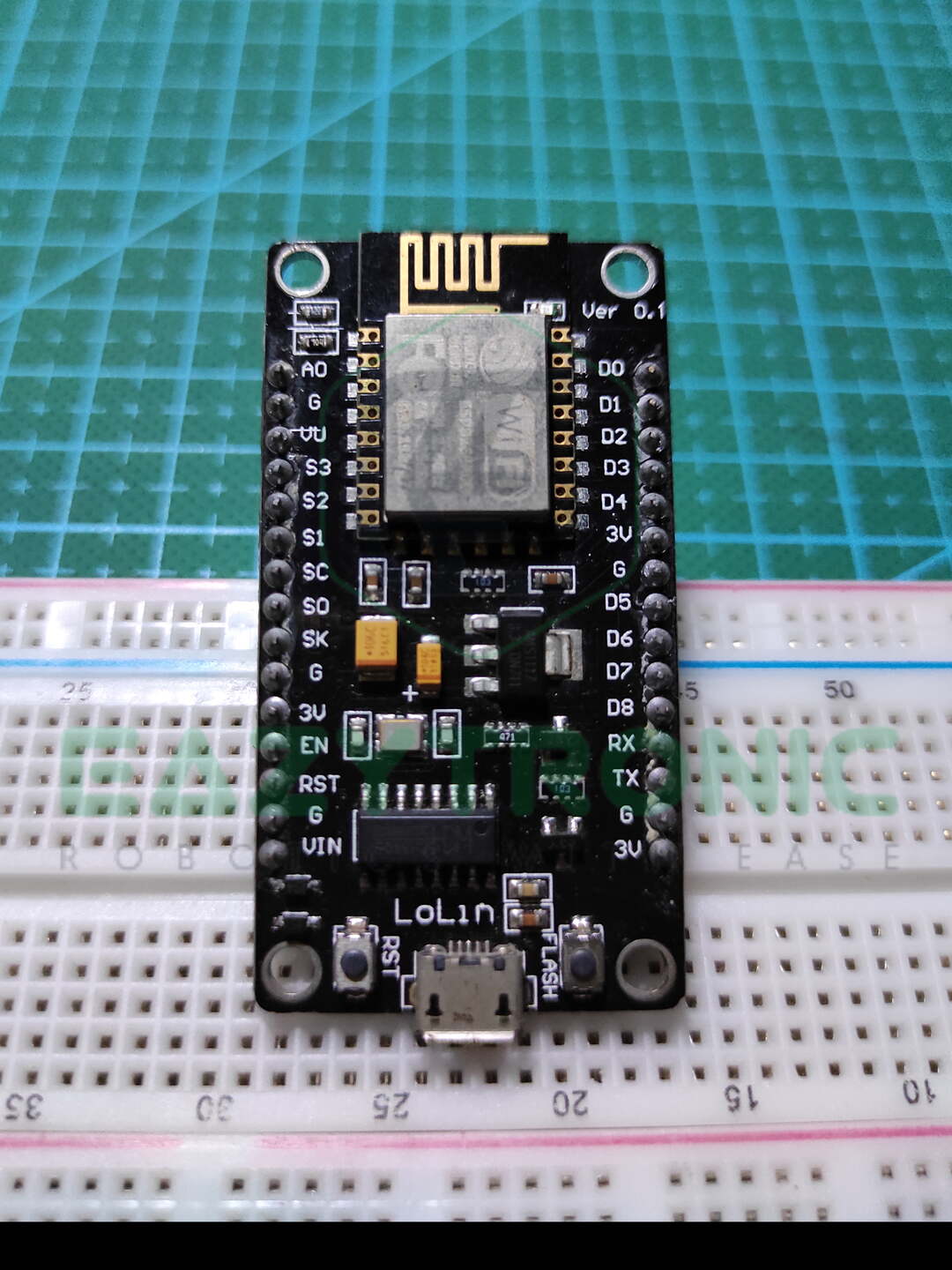
As mentioned, above all the boards are based on ESP8266 SoC, but the difference is in their pins available and other important features. NodeMCU Dev kit is one of the popular development boards with Wi-Fi capabilities. It is built out of the ESP-12E Module, which is a version of ESP8266 Soc. Keep in mind that I’m talking about the NodeMCU Devkit board as a whole. If you take a close look at the board, you’ll observe that an ESP-12E module is soldered onto it. ESP-12E Module is built using ESP8266 SoC, which holds Tensilica Xtensa LX106 32-bit RISC Microprocessor. It operates at a clock frequency of 80MHz—160MHz which can be adjusted, also it supports RTOS(Real-Time Operating System).
Moreover, it has 128 KB of SRAM which is divided into two parts 32 KB & 80 KB. This is because 80 KB of SRAM is used in running the NodeMCU firmware. While under normal conditions, i.e., when ESP8266 is in station mode and connected to a router, available SRAM is around 32 KB. In addition to this. It has 4 MB of Flash which is enough for storing all data including data required for creating a webserver. This memory is further divided into different memory sections like SPIFFS and OTA. Furthermore, you can also attach a separate SPI Flash storage to it if needed. On the other hand, you can also replace the default SPI flash, which is soldered onto the board by default.
Wi-Fi Specifications
Irrespective of its size, it has quite a good Wi-Fi range, both for Station and Access point mode. This adds to its versatility as it has an integrated 802.11b/g/n Wi-Fi Transreceiver which enables it to create an Access point for other devices. Moreover, an onboard antenna for Wi-Fi is also provided on the ESP-12E module. This antenna is good enough, but if you want, you can also attach an IPX antenna by soldering the connector to the Module. Below is the complete data, which is explained here and above in tabular form for brief information.
Power
This board is quite compact, so developers keep in mind that it consumes less power and does it work fantastically. The operating voltage of the ESP-12E Module ranges between 3.0V—3.6V, with a recommended voltage of 3.3V. In addition to this, the peak current of the board with all the feature working normally is around 80mA. This overall configuration of the board makes it optimal for battery-operated devices. Also, if we talk about powering this device like any other board, this can be powered with 5V.
As it includes a 3.3V LDO which converts 5V to 3.3V with a supply current of 600mA. So you don’t have to worry about peripheral modules or sensors you connect to it, it can handle them. But don’t connect too many of them, as it may result in the failing of LDO due to over-current. For powering the board externally you can use the Vin PIN of the board like the other breakout boards Arduino. But unlike them, you cannot power it with a high output power supply like 12V, 2 amps, it will fry it up.
USB to UART
This section is quite interesting as it holds the part where ESP-12E communicates with a Computer or Laptop. Like in the Arduino tutorial, we have seen a USB to UART converter IC used. Similarly, here CP2102 IC is used for this purpose, In addition to this, two pins i.e., RST and DTR PINS of CP2012 are used during uploading the program onto the ESP-12E Module. As the whole system works on 3.3V, this IC also works on the logic level of 3.3V (3.0V-3.6V).
CP2102 can also be replaced by an FTDI programmer like RS232, but the connection is the same as with the original IC. Moreover, there are several other versions, or we can say clones of this board which use CH340G serial converter IC. CH340G IC is commonly used to create clones of the board as it has all the common features used to program most of the boards. Drivers for CH340G and CP2012 are provided below, make sure to download the latest versions of those.
PINOUT
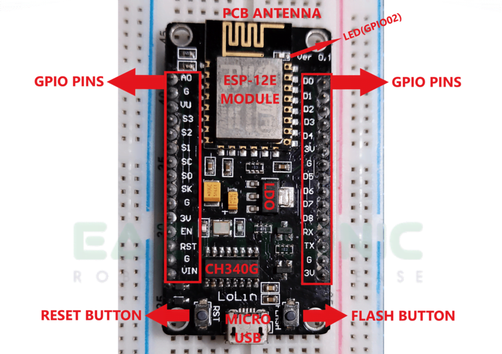
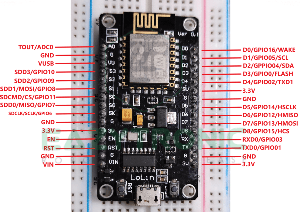
Now let’s talk about the available PINS and functions of GPIO available on the ESP-12E Module. So if we talk about the ESP-12E Module unilaterally, it has 22 pins, whereas the breakout board or NodeMCU Devkit has 30 PINS. The pinout for both is attached below with all the pins marked out. Also, other important components on the board are marked out. Moreover, it supports Pin Multiplexing, this features enable the pins to be configured as different types for different devices. You learn more about it further.
As in the image below, let’s start from the left side, I’ll explain the function of each pin so don’t worry, sit back and enjoy.
Analog PINS
The very first PIN on the Left Side is Analog PIN. The very first drawback of the ESP boards is that they only have one Analog PIN. ESP8266 is embedded with 10-bit precise SAR ADC. Now this term SAR, isn’t it confusing?
SAR stands for Successive Approximation Register, these are better than Sigma-Delta ones. Hence, these ADC are now used in various embedded IC like Atmega328P also. SAR ADC can operate at low power & have high resolution and accuracy. I think most of you know what a 0-bit ADC means, but for those who don’t know, 10-bit stands for 210 = 1024. That means, the values on this pin can be read into 1024 steps ranging from 0-1024 according to the input voltage signal.
Power PINS
If we look at the Power PINS available on the NodeMCU Board (Clone LOLIN), there are plenty of them. On the complete board, there are 3, 3.3V pins along with 5 GND pins. In addition to this, there is a Vin PIN which can be used to power the board using an external power supply or battery. Along with this, there is a VU PIN on the LOLIN Clone board which outputs the Voltage coming from the micro-USB Port.
To supply power to the Module, as well as the sensor or peripherals you connect it needs power. For this, a 3.3V LDO is included in the Board circuit which can supply a current of 600mA. But as mentioned above you cannot connect many sensors with high current consumption as it’ll lead to overcurrent from LDO and can result in failure of LDO. In addition to this, the Vin PIN of the breakout board must not be connected to high power output power adapters, it is recommended to use either 5V or 12V under 1Amp power ratings.
SDIO PINS
SDIO, stands for Secure Digital Input/Output Interface, using these pins you can directly communicate with SD cards without any need for SD card readers as in the case of Arduino Boards. As stated above, ESP-12E supports Pin Multiplexing, therefore these pins can be configured as SDIO pins and GPIO pins depending upon the need of the user. Supported cards are as follows 25 MHz SDIO v1.1 and 50 MHz SDIO v2.0, and 1 bit/4 bit SD mode and SPI mode. Below is the table of the PIN with their respective functions.
| PIN Name/ Module PIN Name | PIN Number | GPIO |
|---|---|---|
| SDIO_CLK / (SDCLK) | 21 | GPIO06 |
| SDIO_DATA_0 / (SDD0) | 22 | GPIO07 |
| SDIO_DATA_1 / (SDD1) | 23 | GPIO08 |
| SDIO_DATA_2 / (SDD2) | 18 | GPIO09 |
| SDIO_DATA_3 / (SDD3) | 19 | GPIO10 |
| SDIO_CMD / (SDCMD) | 20 | GPIO11 |
Control PINS
There are a few pins that play crucial roles in the working of the NodeMCU Breakout Board. This includes Chip Enable(EN), Reset PIN (RST), & WAKE PIN. The functions of these pins are crucial.
Chip Enable (EN): – This pin is used to configure the working state of the ESP-12E Module. HIGH/ON chip works normally, LOW/OFF, the chip consumes small current or works at low current consumption.
Reset PIN(RST): – This pin resets the ESP8266 Chip (ESP-12E Module in whole). Like any other board, this pin can be used to reset the board.
WAKE PIN : – this pin is used to wake the Module from deep-sleep
In addition to these, there is another PIN i.e., GPIO0 which is used during uploading the code to the chip. Hence, it shouldn’t be connected to anything during the program is being uploaded to the chip.
GPIO & PWM
NodeMCU breakout board has 17 GPIO pins which can be configured according to the user’s needs. Like any other boards, these pins can be configured as INPUT, OUTPUT, and INPUT_PULLUP. Furthermore, you can also assign them as INPUT_PULLDOWN, HIGH IMPEDANCE, and also as edge-trigger and level trigger to generate CPU interrupts. In addition to this, ESP8266 supports PIN Multiplexing, so you can assign a single pin as different for different communication i.e., I2C, SPI, UART, I2S, and many more.
Now about PWM, this is the second drawback I felt so far, it has a very less number of PWM pins. Unlike Arduino Boards, this Board only has 4 channels of PWM. GPIO04, GPIO12, GPIO4, and GPIO15, only these pins can output PWM signals. The frequency of the PWM signal can vary in the range of 100Hz to 1kHz.
UART
| UART0 | UART1 |
|---|---|
| RXD0 | – |
| TXD0 | TXD1 |
NOTE:- UART0 is used for programming the chip, so make sure don’t connect them during the upload process. UART1 has only a TXD pin, Hence it is used to print the output only or in simple words log.
I2C
| Funtion | PIN |
|---|---|
| SCL | GPIO5/D1 |
| SDA | GPIO4/D2 |
I2S
| PIN Name | PIN | GPIO | Function |
|---|---|---|---|
| MTDI | 10 | GPIO12 | I2SI_DATA |
| MTCK | 12 | GPIO13 | I2SI_BCK |
| MTMS | 9 | GPIO14 | I2SI_WS |
| MTDO | 13 | GPIO15 | I2SO_DATA |
| U0RXD | 25 | GPIO03 | I2SO_BCK |
| GPIO2 | 14 | GPIO02 | I2SO_WS |
SPI
| PIN Name | PIN |
|---|---|
| MOSI | GPIO13/D7 |
| MISO | GPIO12/D6 |
| SCK | GPIO14/D5 |
| CS | GPIO15/D8 |
Clock frequency can be upto 80MHz and lower
NOTE:- Mode of SPI communication will be explained in basic electronic article.
Blink Led NodeMCU in Arduino IDE
I have already explained how to install and set up Arduino IDE in Arduino Tutorial. If you haven’t even downloaded the Arduino IDE, then follow the instructions in the previous article. Moreover, I have also explained the various section of Arduino. In today’s article, I’ll explain how to install Boards in Arduino IDE. In addition to this, I will also provide a link to download the CP2102 and CH340G drivers.
Installing drivers
If you have an official NodeMCU devkit board, then you’ll have CP2102 USB to UART IC. Some Computers and Laptops easily detect these chips as their rivers are pre-installed. But if Board doesn’t appear in Device Manager, then check for the drivers. You can download the latest version of the drivers from the official website of the IC manufacturer, i.e., Silicon Labs. CP2102 Drivers.
On the other hand, if you have a clone of NodeMCU like the one I have, then you’ll need CH340G drivers for this click the below link and download the latest version. CH340G Drivers.
Adding custom board core on Arduino IDE
For this open Arduino IDE preferably blank sketch or the Blink sketch from examples like in the Arduino Tutorial. Before this, make sure that you have downloaded the latest version of the Arduino from the official website. Furthermore, also make sure that all the Libraries and Boards definitions are up-to-date. After this, you can proceed with steps that’ll guide you on how to install the ESP8266 board’s core in Arduino IDE.
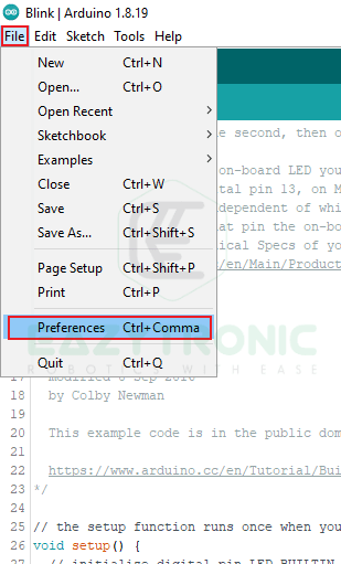
Now under the file menu, you’ll see the preferences option, as shown in the image below. Once the preference dialog box appears, enter this link into the Additional Boards Manager URL text box.
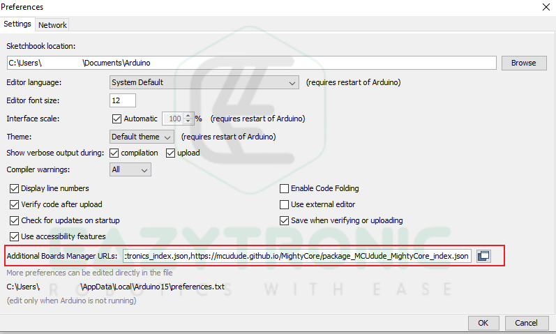
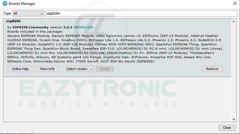
http://arduino.esp8266.com/stable/package_esp8266com_index.jsonIn the image above, I have entered many board URLs, so disregard the ones in the image. After this, press ok and open Boards manager to install the board’s core. Under Tools > Boards, Open Boards manager, and in the search box type ESP8266. You’ll see a board definition like in the image below, I have already downloaded it. You’ll see an install button, using this install the latest version of board definitions and wait for the process to complete.
Blink LED Sketch
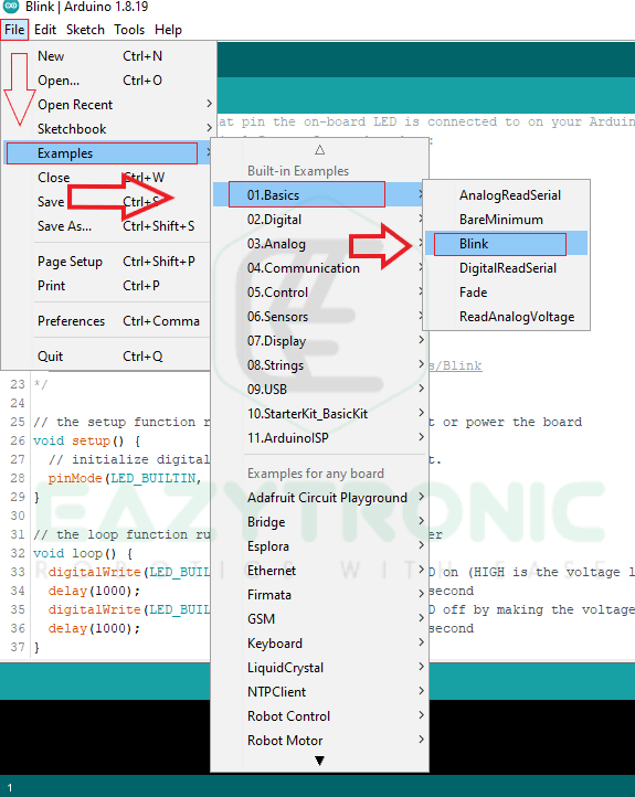
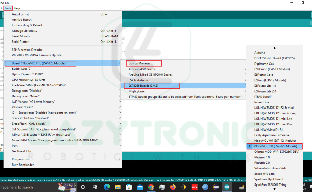
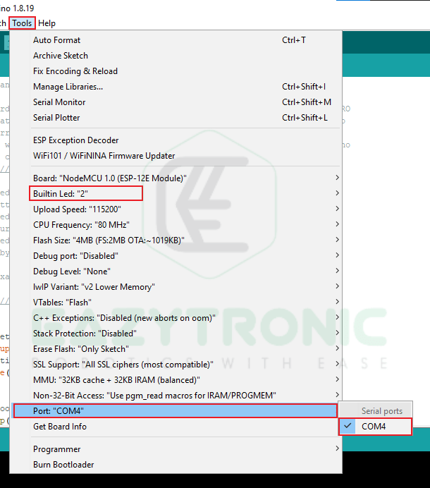
After this, open the Blink sketch from the File menu > Examples > Basic > Blink. Select the board and port as shown in the image below and upload the code. Just make sure you have selected the correct pin for the LED. If you are using the onboard LED, then during selecting the port make sure to check the LED GPIO option there.

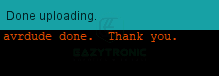
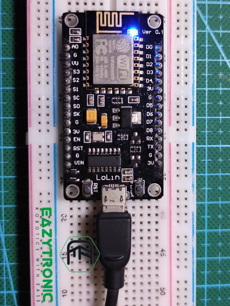
Once the upload process completes, the LED on your board will start blinking with a time interval of 1s.
With this, we sum up our intro article on ESP8266. I have provided all the information and hope you like it. If you find something missing, do comment down below, and I’ll add it asap.