
Hello Learners, Welcome back, today we’ll introduce ESP32 to you. ESP32 is another very popular and interesting Development, It is an advanced version of the ESP8266 NodeMCU Board. It is the successor of the NodeMCU Board which we have already discussed in the previous article so make sure to read it. It is perfect for IoT devices, or better than ESP8266 NodeMCU due to its more features. Moreover, the cost which is the main constraint for many people is simple in budget. So let’s explore it further.
What is ESP32
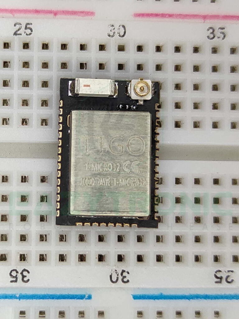
ESP32 is the name that comes to mind after NodeMCU ESP8266 for high-quality and demanding projects. In the previous article, i.e., NodeMCU ESP8266, we learned that it is the in-budget controller for IoT devices. Similarly, it is a budget-friendly Development board with even more features, like the NodeMCU. Not only it can be used for Wi-Fi controlled devices, but can also be used to control devices via Bluetooth. These features and other adds up to the value of this Development Board. Now in the market, there are various versions of ESP32, I have 3 different versions but for basic let’s take up the basic model.
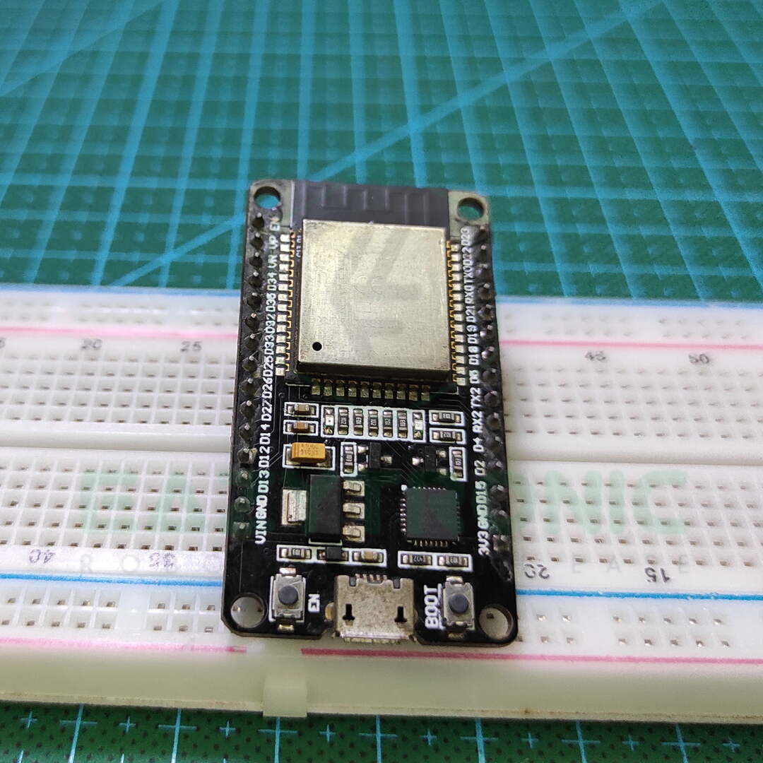
ESP32-WROOM-32 is the basic Module that comes in the Development board. Moreover, it is quite famous and very easily available. The Module is similarly soldered onto the Development board, like in the case of NodeMCU. In addition to this, the ESP32-WROOM-32 Module is developed by the same company, Espressif Systems. All the series of the ES32 Boards are based on ESP32 SoC which is the same for all Modules but the only difference in version revisions and other features. In addition to this, most of the ESP32 Modules have the same pinout, so there is no need to confuse about the pinout.
Specifications of ESP32
Now we’ll learn about the technical and physical specifications of the ESP32 Module. This section is similar to the NodeMCU one, but additional features of the ESP32 will also be added. Firstly, the ESP32-WROOM-32 Module has a Tensilica Xtensa 32-bit LX6 Dual-Core microprocessor. The core is an upgraded version of ESP8266 as it has 2 cores and can be operated at a variable clock frequency of 80MHz-240MHz. Both cores can be operated individually and can perform tasks independently.
I don’t want to go into technical terms, so in simple words, it has integrated Power amplifiers, Low-Noise signal amplifiers, Filters, and many more. In short, it is packed with all the necessary components that a beginner would need to practice. Below is the attached datasheet of the Module, you can have a look at it for more detailed information.
Moreover, like ESP8266 it works on RTOS, but the version it supports or specifically developed for it is freeRTOS. Though it has all these features, packed with these features and many more discussed further. Yet, it is small and can be used in compact devices such as wearables (smartwatches). It has 448 KB ROM for Booting and Core functions, and 520 KB of SRAM for Data and instructions. In addition to this, it has separate 8 KB of RAM for RTC (RTC_FAST & RTC_SLOW 8 KB each). Moreover, it has external 4 MB of external flash soldered within the Module enclosure. This is enough for all the functions and instructions, including creating a host and access point using ESP32.
Wi-Fi & Bluetooth Specifications
Now it’s time to learn about Wi-Fi and Bluetooth specifications, this Module has greater capabilities irrespective of its size. ESP32 has an integrated 802.11b/g/n Wi-Fi Transceiver with a transfer speed of up to 150Mbps. With all these specifications, it is not only able to connect to Wi-Fi but also create an Access point of its own. Moreover, there is also an onboard PCB antenna which provides a good range. Or you can also connect an IPX connector for an external antenna. In addition to this, it also has a Wi-Fi Direct feature, this type of connection is a good alternative for creating an access point i.e., for peer-to-peer connection.
Bluetooth, the second most type of connection for IoT devices, it also encloses many Bluetooth features. Bluetooth 4.0 (BLE) & Bluetooth Classic are the most used ones. Moreover, you can also use Wi-Fi and Bluetooth features simultaneously without much effect on their usage and range.
Power
If we talk about the operating voltage and power consumption, it is slightly different from that of ESP8266. The operating voltage for ESP32 Module ranges from 3.0V—3.6V, with a recommended voltage of about 3.3V. This voltage level is quite common for wearables and compact devices, also almost all sensors can work at this voltage. The current consumption of the board is about 80mA under normal usage, i.e., listening to Wi-Fi and Bluetooth clients. Moreover, it can reach a max limit of up to 240mA—260mA during the Access point mode and Bluetooth transfer.
All these operations require a large amount of current consumption, and along with the sensor attached to the module, the current consumption increase. Therefore, a 3.3V LDO is provided on the Development Board of the ESP32, which can supply up to 600mA of current. But make sure not to connect the sensor that can fail the LDO due to Overcurrent. Hence, make sure the current drawn is under the limit of LDO. In addition to this, you can also connect an external battery or power supply to the board via the Vin PIN. Or, you can also use the micro-USB port for delivering power via a 5V supply. In both cases, make sure you do not use high-rating power supplies like 12V 2 amps, as these may damage the board over time.
Serial communication / USB to UART
This is the section where all the fun begins, as it contains the serial communication IC. Like all the other Development Boards, this one also has an IC for serial communication between your laptop or desktop and the Board. Like in the case of ESP8266, this also has CP2102 Serial IC, also in various clones, you may see CH340G IC. The latest drivers for both can be found on their official website, which is mentioned later in the article. In addition to this, both ICs can easily work on a 3.3V logic level.
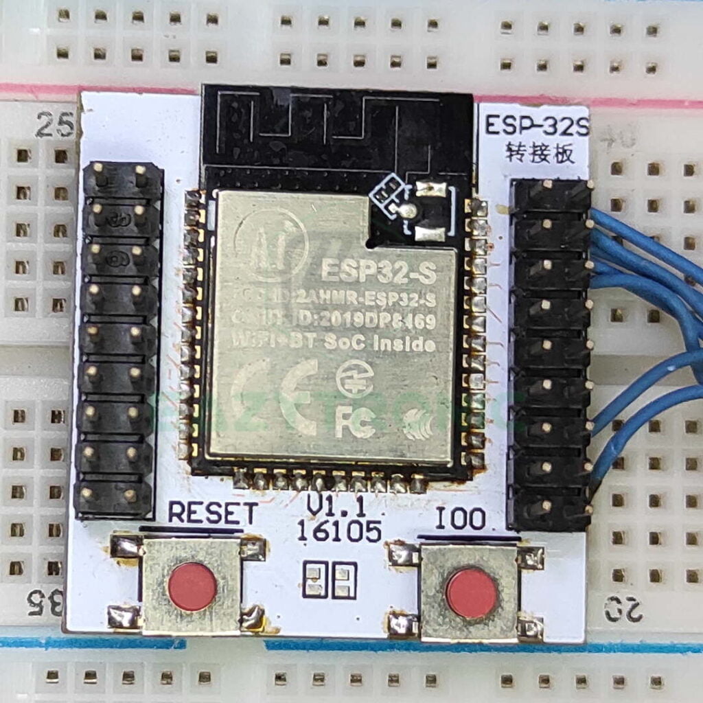
Moreover, you can also use other FTDI programmer to program the Modules separately, as I do in my case. But using those or either the official ones like CP2102, you have to make proper connections. What I mean is that, unlike Arduino boards, these boards require additional PINS that are DTR and RST. These pins are connected to RST and GPIO0 of the Module during the uploading of the program. The one I’m going to explain is the original one, i.e., ESP32 Devkit. Also, I have two other versions which I program using the FTDI programmer, so how to program them using FTDI, which I’ll explain in another article.
PINOUT
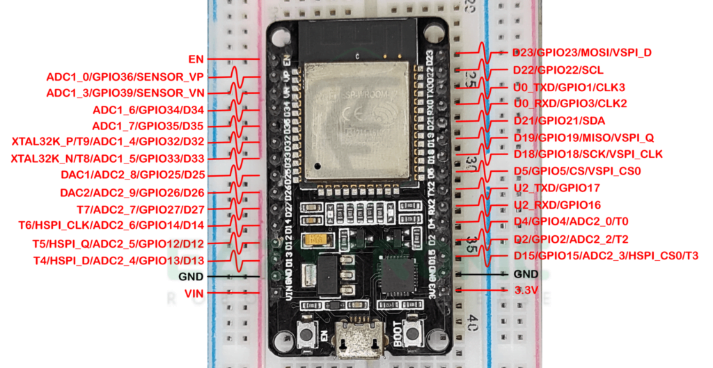
PINS, is the main issue for many Development boards, as a developer needs many pins, but they aren’t available. Don’t worry, it is not the case with ESP32, it has enough pins to connect many numerous sensors altogether. Although the ES32-WROOM-32 SoC has 48 pads(SMD PINS) only 38 of them are available on the ESP32 Module and finally only 30 on the ESP32 Devkit Board. These 30 pins include all the PINS required for all sorts of communication and connection. Moreover, like ESP8266 it also supports PIN Multiplexing, which means a single PIN can be assigned or used differently in different communication.
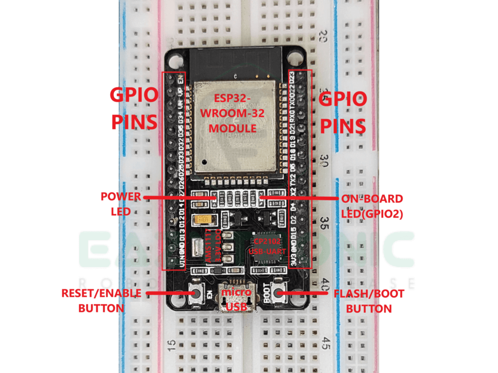
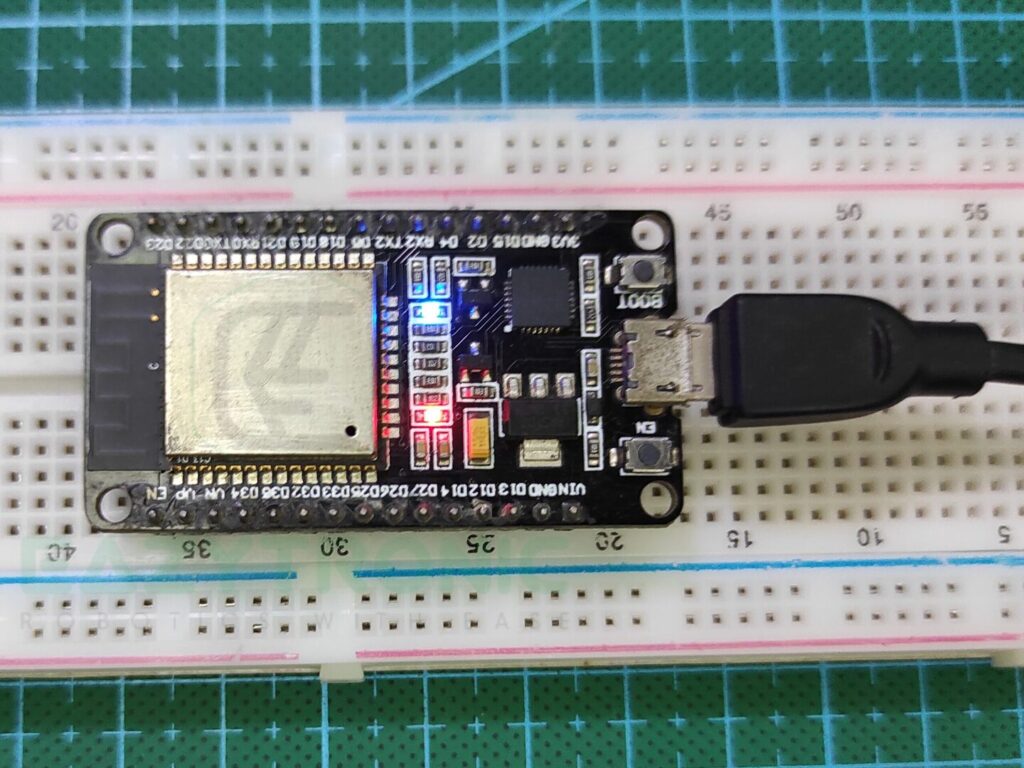
Below is the attached Image of the ESP32 devkit, It is the official version. So I’ll be referring to this and giving you as far as information. Along with this, there is also an onboard LED that is connected to the GIPO2 of the ESP32 Module. In addition to this, there are also two button RESET and FLASH/BOOT, both of them has definite functions.
Analog PINS
This is the advancement from the ESP8266 Module, which has only a single analog PIN. But not anymore because ESP32 has numerous Analog PINS via pin multiplexing also enhanced resolution. ESP32 has 15 channels of ADC with a 12-bit resolution. For those who don’t know what 12-bit states, it refers to 212 =4096. In simple words, the values read by the ESP32 range from 0-4096, which were 0-1024 in ESP8266.
Just like ESP8266, it has SAR ADC, which is now in most of the Development boards. Moreover, these pins of the ESP32 can be used to make a gain amplifier for low-range signals, such as a condenser microphone. In addition to this, these PINS can also measure voltage in sleep mode, this is certainly an advancement from ESP8266.
POWER PINS
Unlike ESP8266, ESP32 have very less, or we can say almost single power pins. The version of Board that I have, has only 1, 3.3V PIN with a total of 2 GND PINS. For powering the board using external power, Vin PIN is provided, also you can use this pin to power the board using the battery. For providing the power to all the components and sensor attached to the Development Board, a 3.3V LDO is included into the circuit. AMS1117, 3.3V, this LDO can provide a max current of about 600mA to the complete circuit. It is the same as in the ESP8266.
But in all cases, you have to make sure to connect a limited amount of sensor to the board such that it doesn’t draw much amount of current from LDO. If that happens, LDO may fail or in worst cases the board gets fried up, damaging another component due to a sudden supply of large current. A micro-USB port provided on the Board can also be used to power the board. But make sure to connect it to the low power rating supplies like 5V, and 12V under 1Amp.
SDIO PINS
ESP32 doesn’t have fixed SDIO PINs like that in ESP8266 but can be assigned to a group of PINS via software. With PIN Multiplexing, it becomes easier to use different pins if one set of pins is used in different communication. Hence, to solve this issue, the complete PINS usage for the different types of pins is provided in the datasheet.
Control PIN
ESP32 has additional control pins as it has many inbuilt sensors and devices which can be operated via dedicated IO pins.
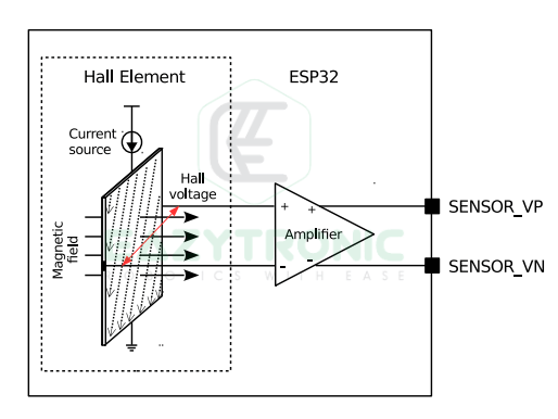
SENSOR_VP & SENSOR_VN:- These are the dedicated pins for the inbuilt Hall Effect sensor. Most of you know what a hall effect sensor is, so these pins can output the data from the hall effect sensor. Below is the block diagram of the Hall effect sensor.
XTAL_32K_P & XTAL_32K_N:- These are the pins provided to connect an external 32KHz crystal for RTC. ESP32 has an inbuilt RTC which can be used to keep a record of time. For this, either you can use the default crystal or connect an external one using these pins, but you have to define the pins in software to use the external crystal.
WAKE:- ESP32 doesn’t have any fixed Wake PINs, because many pins can be used as WAKE PINS in different conditions. Furthermore, the PINS that can be used to Wake ESP32 from deep sleep are mentioned in the table. For this, refer to the ESP32 reference manual under section 31.3.10.
RST:- Reset PIN is a must in every Microcontroller as it is used during uploading the code. Also, reset the microcontroller or restart the code from the beginning. ESP32 doesn’t have any physical reset pin, only it has a RESET button.
Chip Enable (EN):- Chip Enable PIN is the same as in the ESP8266. This pin is used to set the power mode of the ESP32 Module. When Pulled HIGH, the Module works normally, whereas when pulled low, the chip works on low power.
CLK2 & CLK3:- These pins are used to provide clock signals for the peripheral devices connected to ESP32 Module in the I2S connection.
GPIO
ESP32 has a total of 48 pads on the ESP32-WROOM-32 SoC, while only 30 pins are available on the fully assembled Development board. As ESP32 supports PIN multiplexing and some embedded sensors like Hall Effect Sensor, RTC, Temperature Sensor, and Touch Sensor. In addition to these, all the other protocols such as SPI, I2C, UART, I2S, SD Card, SDIO, PWM, ADC, DAC, and many other features can also be performed using these PINS. In short, if we say, it is compact sized full of features boards ideal for every IoT device.
PWM
This is again an advancement from the ESP8266 Board where it was only 4 PWM channels, It has 25 PWM Channels. In simple words, it covers almost all pins available on the Development Board. All the 25 channels can drive each pin individually with separate PWM Timers, and PWM operators. As ESP32 has a 12-bit resolution, the values range from 0-4096, which means now you have more accuracy in controlling the motor.
DAC
Digital to Analog converters, these pins can convert a digital signal to analog just like the reverse of Analog Pins. ESP32 has 2 channels of 8-Bit DAC. These PINS can output the analog signals corresponding to the digital signals. Moreover, both the DAC channel can work independently.
Touch PINS
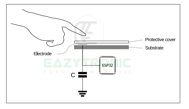
This is an additional feature of ESP32 which is absent in ESP8266. ESP32 has 10 capacitive touch channels, which are similar to a touch sensor. While the 30-pin version of ESP32 Devkit only has 9 Capacitive touch pins(GPIO0 not present). These pins can be connected in the following way, shown below, to be used as a touch sensor. Below is the table of all the touch pins.
| Touch PIN | GPIO |
|---|---|
| T0 | GPIO4 |
| T1 | GPIO0 |
| T2 | GPIO2 |
| T3 | GPIO15 |
| T4 | GPIO13 |
| T5 | GPIO12 |
| T6 | GPIO14 |
| T7 | GPIO27 |
| T8 | GPIO33 |
| T9 | GPIO32 |
UART
| PIN | UART0 | UART1 | UART2 |
|---|---|---|---|
| TXD | GPIO1 | GPIO10 | GPIO17 |
| RXD | GPIO3 | GPIO9 | GPIO16 |
NOTE:- UART1 requires reassignment of pins for the UART1 to be useable. All the information about UART communication is provided in the UART communication article.
I2C
| PIN | PIN Number |
|---|---|
| SCL | GPIO22/D22 |
| SDA | GPIO21/D21 |
I2S
ESP32 has 2, I2S ports which can be used to communicate with I2S devices. PINS for this communication can be assigned using the software.
SPI
| PIN | HSPI | VSPI (Default) |
|---|---|---|
| MISO/Q | GPIO12/D12 | GPIO19/D19 |
| MOSI/D | GPIO13/D13 | GPIO21/D21 |
| SCK | GPIO14/D14 | GPIO18/D18 |
| CS | GPIO15/D15 | GPIO5/D5 |
BLINK Led ESP32 in Arduino IDE
First things first, Arduino IDE is the most common and very famous software which we use to program most of the Boards. ESP32 can also be programmed using the Arduino IDE, but first, you need to install the ESP32 Board Core into the Arduino IDE. Before this, make sure you have installed the Arduino IDE and set it up. Also, make sure to install and update all the existing board definitions and libraries. All of this I have already explained in the Arduino Tutorial, make sure to read it if you haven’t set it up.
Installing drivers
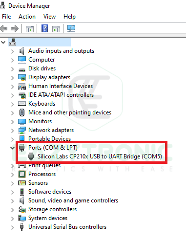
For installing the board driver, make sure you have the previous version uninstalled. The links for the drivers for both CP2102 and CH340G are hyperlinked to their official websites. Some computers also have the CP2102 drivers preinstalled, so check it. For this, connect your board to the computer or laptop and in the device, the manager check for PORTS & COM in it.
Installing ESP32 Board Core in Arduino IDE
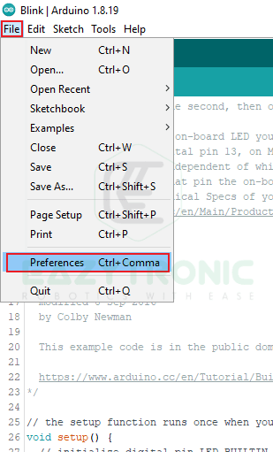
Under File Menu, go to the Preferences option and click on it. Now a dialog box will appear.
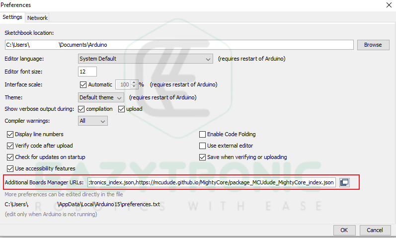
In the Additional board URL, add the following URL to add support for ESP32 Boards. This will show up on ESP32 boards in Boards manager.
https://raw.githubusercontent.com/espressif/arduino-esp32/gh-pages/package_esp32_index.jsonNow open Boards Manager from the tools menu under boards and then Boards Manager.
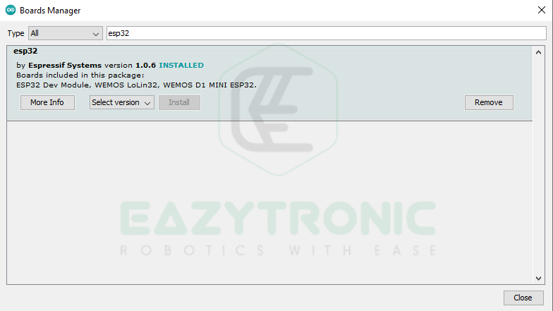
Search for ESP32 and a Boards Definition will show up. Install this boards and wait for installation to complete. Once the installation complete, you can continue to next step.
BLINK LED sketch
Open blink LED sketch from the File menu > Examples > Basic > Blink
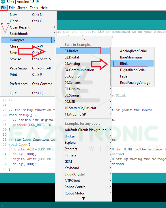
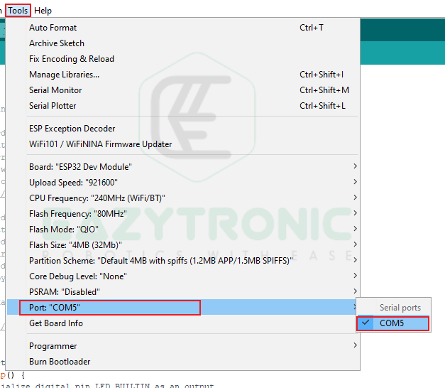
After this, select your Board as in the images shown below. Along with this, select the COM Port it is connected to. While selecting the PORT, make sure to select the Built-in LED pin also as shown.


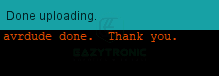
Now finally hit the Upload Button and wait for the uploading to complete.
After this, the LED will start blinking on the ESP32 DevKit.
With this we have completed the introduction on ESP32 Boards. I hope you’ll like it, and if you want any specific information to add, just comment down below.