
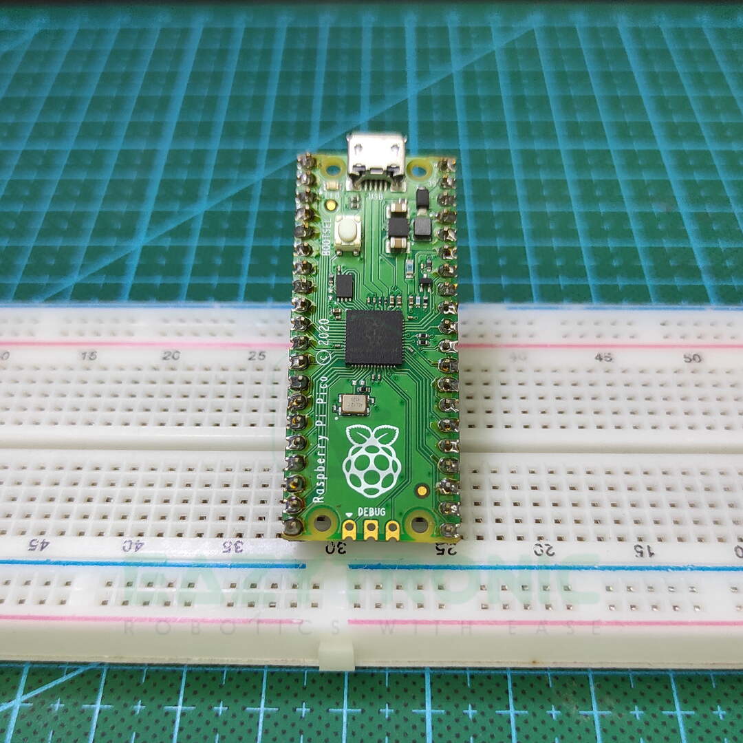
Hey Folks, Today we’ll start the introduction of Raspberry Pi PICO. Raspberry Pi PICO is another Development board that gained popularity. Raspberry Pi PICO is based on an RP2040 microcontroller, which is much more powerful than the Arduino UNO. Also, there are other versions like PICO W that come with an inbuilt Wi-Fi chip for IoT features. This can be programmed with either C/C++ or most commonly in MicroPython. MicroPython is somewhat similar to Python, so I hope Python learners wouldn’t face any such issues. So, without boring you, let’s head to the main topic.
What is Raspberry Pi PICO, RP2040?
Until now, many of us have heard about the most famous single-board computer, Raspberry Pi boards. Raspberry Pi 3 and Raspberry Pi 4 are the latest versions of these single-board computers. Raspberry Pi PICO is similar to other Boards like Arduino UNO, ESP32, ESP8266, or STM32, but it is quite more powerful than these. Also, as this is compatible with python, it can be used by a new programmer who lacks C/C++. Moreover, many of us have seen simple projects like interfacing some sensors and other stuff like this, but buying a $35 board is not smart. For this, Raspberry Pi org has released a $4 Microcontroller board, Raspberry Pi PICO.
Raspberry Pi PICO is based on RP2040 Microcontroller that can be compared with ESP32 boards in head-to-head competition, but I recommend both for a hobbyist. The RP2040 IC name also has some other meanings, that can define many things about IC architecture. RP stands for Raspberry Pi, 2 indicates that the IC has Dual Core, 0 type of core i.e., M0+. In addition to this, it also defines the storage and memory of the IC that can be recognized as follows, 4 indicates the floor value or largest integer value of log(RAM/16 KB) that comes to 4. Moreover, the last 0 in the name stands for the onboard non-volatile storage. But as there is no on-board storage hence this value is 0, but it can be calculated as the floor value of log(non-volatile/16 KB).
Specification of RP2040
RP2040 is a microcontroller from the same Raspberry Pi Organization, moreover is it cheap and as capable as an ESP32. Firstly, RP2040 is built around Dual-Core ARM Cortex M0+ that runs at a clock frequency of 133MHZ. Unlike ESP32, its clock frequency cannot be adjusted, also the pin numbering is sometimes complicated PICO. There is another version of Raspberry Pi PICO available which is launched recently, i.e., PICO W. PICO W is the Wi-Fi inbuilt version of the Raspberry Pi PICO. I do not have that version at this instant, so all the information regarding PICO W will be updated later.
Moreover, it has 264 KB of SRAM with six independent banks and can support up to 16 MB of an external flash. RP2040 comes in the QFN-56 Package, out of which 30 GPIO pins are available. In addition to this, it also has 4 ADC channels for controlling Analog devices. Lastly, it can also support all types of communication like UART, I2C, SPI, and PWM. Moreover, the PICO W version can also support all Wi-Fi functions that an IoT device should have. Also, there are several other features that we’ll discuss later in the article. Below is the attached Datasheet of the RP2040 IC, which contains all the detailed information. If someone is interested, then they can read it.
Specifications of Raspberry Pi PICO
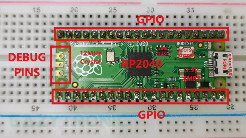
Some of you might be wondering that we have already discussed this section above, but that was for RP2040 IC unilaterally. This section contains information regarding the board as a whole. So first about GPIO Pins, as I have already told you that the RP2040 IC comes in a QFN-56 package. But the Overall board only has 40 GPIO Pins and 3 debug pins. Moreover, the RP2040 can support up to 16 MB of an external flash. However, the board comes with an external 2 MB of flash. Which on the other hand seems to be less than compared to ESP32 & ESP8266.
In addition to this, the pin’s shape is similar to that of the ESP32 & ESP8266 Modules, which means castellated. Castellated Pins allow you to solder the Module or board directly to your project circuit without considering essential parts like power supply etc. As these all parts are available on board like the Arduino Nano. Hence, it is ideal for a small-scale project which needs replacement from Arduino Nano.
Power
Now let’s look at the power pins and input sources available on the board. If we look at the board there are only a few positive input/output pins but GND pins are evenly distributed. Numerically, there are 8 GND Pins, along with this there are two 5V or Input Supply pins. These pins can output the same voltage as the micro-USB input. Moreover, you can also use a VBUS pin to power the board using the external power supply up to 5V. In addition to this, the VSYS pin voltage varies from 1.8V-5.5V, which is used by the onboard SMPS to generate 3.3V. Below is the attached Datasheet of the Raspberry Pi PICO.
Raspberry Pi PICO board, an onboard Buck-Boost converter that can provide the board with a stable 3.3V power supply to continue working. This is certainly an advantage over all the other development boards, as all other boards don’t have a buck-boost converter. This buck-boost converter can provide up to 800mA of current for the complete board and sensor attached to it. In addition to this, there is also a 3.3V output pin for the sensors that are only 3.3V tolerant. So on the whole, it has quite an acceptable set of power pins also many other features are unique to it.
Serial Communication
Now this section is quite interesting as it contains details about How the RP2040 IC or the Raspberry Pi PICO development board communicates with the computer. Unlike other boards it doesn’t require any USB-to-UART IC, rather the RP2040 IC has dedicated pins for that purpose. RP2040 has an integrated USB1.1 PHY and controller which can be used in both Device and Host mode. Moreover, this connection is then converted into the micro-USB port by connecting two 27 Ω resistors in series. You can also access the boot ROM of the RP2040 in the BOOTSEL Mode, aka USB Bootloader. In addition to this, you can also access external USB devices by making the Raspberry Pi PICO work as a host.
PINOUT
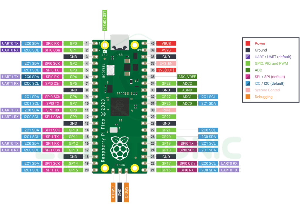
Raspberry Pi PICO has numerous amount of pins available for all functions that can be compared to ES32 series boards for the number of pins. It is built around RP2040 IC which comes in a QFN-56 package. But the final development board only has 40 PINS, as some PINS are used for internal functions. For more information refer to the datasheet provided below. Moreover, there are 3 Debug pins that you can use along with Raspberry Pi 4 board to debug the errors. The main thing about using the PICO board is that you can program the board either using MicroPython or C/C++.
Below is the attached GPIO pinout from the official Raspberry Pi documentation. As this is open source, so all the files required to replicate such a board yourself can be found on their website. The board also has an Onboard LED just like any other board and a Reset button. This button is special as it can perform many tasks, which is explained in the programming section below. Furthermore, the RP2040 IC requires a 12MHz crystal oscillator or resonator to work. You can also mount the development board just like the Arduino UNO, and ESP32 boards as there are mounting holes present on the board.
Analog PINS
Analog Pins are the main concern while handing the Analog output value sensor, more importantly, the resolution plays a major role in it. In Raspberry Pi PICO there are 4 Channels of ADC, this is the same as the other development boards so far I have discussed. However, out of 4, only 3 pins are on the final development board which you can use. More specifically, it also has SAR ADC with a 12-bit resolution. What does 12-bit mean, I have already told you in the ESP32 introduction article. Therefore, the value it reads ranges from 0-4096 which is more accurate than the Arduino UNO 10-bit ADC. In contrast, the development board works purely on 3.3V. Hence, the values it read are according to the 3.3V logic level. Therefore, make sure to connect only 3.3V logic-level analog devices, or else you may damage the pins.
UART
UART interface is the most common for all the microcontrollers and development boards. However, previously we have learned that there is no USB-to-UART IC, so how is it possible? Although the RP2040 directly communicates with the Computer as it has an embedded USB interface, yet it can use UART communication. In addition to this, there are 2 UART ports for connecting two devices simultaneously. More information regarding the working of the UART interface is given in its dedicated article. Like ESP32, Raspberry Pi PICO also supports Pin Multiplexing, which is good for upcoming microcontrollers.
Due to this, there are a few sets of pins that can be assigned as the UART port pin as shown above in the pinout. Furthermore, in other communications also this is the same case. Thus, you can use the different sets of pins if one set f them is occupied.
GPIO
Another interesting section is the GPIO pins available in any microcontroller. In Raspberry Pi PICO, there are 30 GPIO pins available for user needs. Most of them support PIN Multiplexing, Hence they can be used differently in different communication. However, all the GPIO pins are only 3.3V logic level tolerant, so you cannot connect them to a device working on 5V. Moreover, while programming, you can initialize the pins either with the GPIO numbering or via board numbering. This is the same as in the Raspberry Pi boards (Single board computers) programming you get two option BCM Numbering or BOARD Numbering. The complete set of GPIO pins is shown in the Pinout above, refer to this for programming and so.
PWM
PWM is the main concern when it comes to making moving projects or anything that requires controlling the moment. In Raspberry Pi PICO, nearly all GPIO pins can be used as PWM pins. It is the same as the ESP32, where also all pins can be used as PWM pins. However, there are only 16 PWM channels, all pins can be used as PWM because of PIN Multiplexing. In addition to this, you can only use 16 pins as PWM simultaneously, exceeding this number may result in an error. This advantage enables the user to use any pins irrespective of concerns about the clashing of pins. The main thing is resolution and reference or logic level voltage.
Like in the previous section, PWM pins work on the 3.3V logic level and can deliver the signal in this range. However, it has a 16-bit resolution, which is quite broad and therefore accurate. 216 = 65536, this is a very huge value and sometimes more frustrating. Specifically, while calibrating the motors or any other actuators, hit and trial among these values is a simple headache. Therefore, if you want to do so make use of the exponent of the values, this may help you a bit.
SPI
SPI is the most common interface available in most of the sensors, also it is faster than UART communication. Raspberry Pi PICO has 2 SPI Ports just like UART ports. Moreover, these ports also support being assigned to a different set of pins under pin-clashing circumstances. The set of pins that can be used is mentioned clearly in the pinout image above. Furthermore, a detailed article about how the SPI protocol works and stuff is mentioned in the SPI communication dedicated article.
Besides this, you also have to make sure you connect devices that are compatible with the 3.3V logic level, as it is the working logic level of the Raspberry Pi PICO. Nevertheless, to avoid damaging the Board and using the 5V logic level devices you can use a logic level shifter, as I’ll be in upcoming projects.
I2C
I2C communication is another most common and popular type among microcontrollers and sensors. This is due to multi-device connectivity and two-line data transfer. Though it lacks in terms of SPI communication, it is still used widely. In Raspberry Pi PICO, there are 2 I2C ports that similarly to SPI and UART can be assigned to a different set of pins according to the circumstances. In addition to this, it can be configured in both Master and Slave mode similar to other microcontrollers.
However, similarly, you can only connect the 3.3V logic level devices to it as higher logic level voltage devices may damage the board. Besides this, you can also use a logic level shifter to avoid this issue.
Control PINS
There are two control pins on the Raspberry Pi PICO development board 3V3_EN & RUN. 3V3_EN pin is connected to the enable pin of the SMPS, which delivers the stable 3.3V power supply. To stop or turn off the SMPS, connect this pin to the ground and the 3.3V stable supply will turn off. RUN pins can act as the RESET pin when connected to GND via a push button. Pressing this button will reset the board. Moreover, this button can also be used as the BOOTSEL button present on the board.
Programming the Raspberry Pi PICO Board
There are two ways in which you can program Raspberry Pi PICO board, C/C++ & MicroPython. I have done programming in both and with experience advise you to use the MicroPython as a preferred one. For this you have to install or upload the MicroPython firmware onto the board, this is explained in detail below. In addition to this, you can use the same procedure to install the firmware on Mac and Linux environments. You can also use a Raspberry Pi SBC for this, but that is a bit complicated, rather use any of the mentioned above. I’m currently using a Windows machine.
Installing Thonny IDE
In the process of programming the Raspberry Pi PICO, you have to install the Thonny IDE. It is a Python programming software just like Python official software, but it can be used to program PICO boards in MicroPython. MicroPython is the part of Python3 language as it can be used to program the microcontroller and programming them using heavy Python libraries isn’t possible. Hence, we use MicroPython, however, both MicroPython and Python are the same and very easy to learn for beginners.
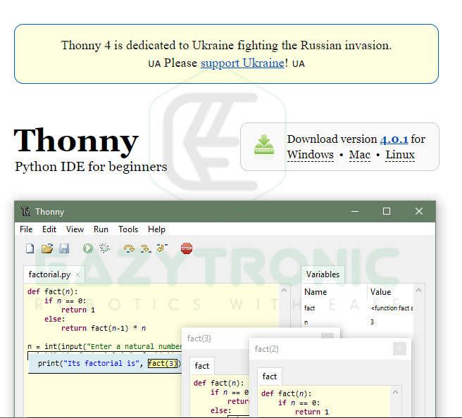
To download the software, head over to the official Thonny IDE website, from there you can choose the required version and download it. Furthermore, you can also use the below features mentioned on their website for more information.
Opening First Time
When you open the Thonny IDE the interface would appear something like this. The various sections of the IDE are mentioned in the image below. The main screen where you will write the code is called Script Mode, in this mode, all your code will be saved in the form of a file. The below section is called the IDLE Mode, in this section, you can execute the line by code. Moreover, the output of the command executed will be displayed at the same time from the Raspberry Pi PICO.
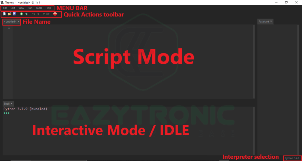
In addition to this, there is also selecting the interpreter for executing the command. In Thonny you can either use the Python interpreter installed into your system or you can also use the Raspberry Pi PICO interpreter to execute the command. Unlike Arduino, you don’t need to install any drivers for the Raspberry Pi PICO as it can be easily recognized by most machines.
Flashing Firmware
For flashing the firmware you can use two ways either directly via the Thonny IDE or in the boot ROM Mode. However, for this, you need to download the firmware file from the official Raspberry Pi website. First with the Thonny IDE.
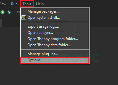
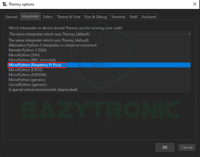
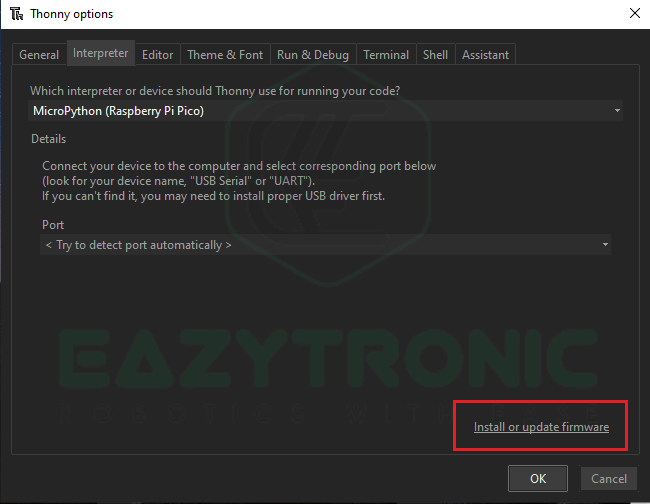
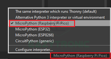
For flashing the firmware onto the Raspberry Pi PICO you need to open the Options from the Tools Menu. Now go to the Interpreter tab in the dialog box that appeared and hold on. After this, from the drop-down box select MicroPython (Raspberry Pi PICO) option from it. You can also there are many other boards supported that can be programmed using MicroPython like ESP8266 & ESP32. Next, Click on the Install or update firmware this will open a new dialog box again.

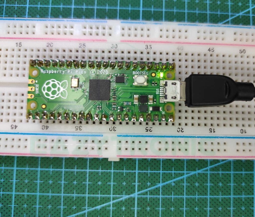
Now grab your Pi PICO and micro-USB cable, while holding down the BOOTSEL (White) Button plug in the USB cable. This will open a new device in the file manager of your system, for this method ignore this and continue. Now you’ll see that some information has appeared on the screen.

Lastly, release the holding button and click on install, now sit back and wait for firmware to completely install. After completing the installation, you can program the board as you want. But before this reinsert the board but this time without pressing any button. Then from the bottom right of the screen select the interpreter, and you are good to go.
Alternate Method
You can also download the UF2 file from the official Raspberry Pi website. After this, just drag and drop it into the boot ROM which appeared as a new device on your computer, when you hold the BOOTSEL button and inserted the USB cable. UF2 File.
Blink LED MicroPython code
Below is the code for blinking the onboard LED of the Raspberry Pi PICO. A detailed explanation of each line is given below.
from machine import Pin
from time import sleep
led=Pin(25,Pin.OUT)
while True:
    try:
        led.value(1)
        sleep(1)
        led.value(0)
        sleep(1)
    except KeyboardInterrupt :
        break
This code is with the sleep time counted in seconds, for using the milliseconds code use the below one.
from machine import Pin
from utime import sleep_ms
led=Pin(25,Pin.OUT)
while True:
    try:
        led.value(1)
        sleep_ms(1000)
        led.value(0)
        sleep_ms(1000)
    except KeyboardInterrupt :
        break
Explanation

In the first line, we import the Pin module from the machine package. This is the necessary module that needs to be imported to interpret the code. Next, we import either the sleep module from time or sleep_ms from utime. This is because sleep measures time in seconds while sleeps_ms measures time in milliseconds.
After this, we initialized the GPIO pin as OUTPUT. In Raspberry Pi PICO Onboard LED is connected to GPIO25. You can change the LED pin and therefore the circuit by connecting an external LED to the board in series with a resistor. Next is a simple while infinite loop with the try and except method. In this, we use the interrupt from the keyboard as the terminating command.
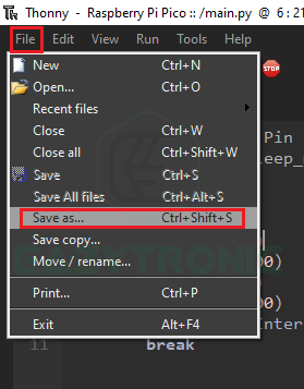

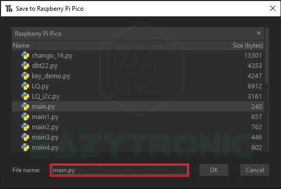
Furthermore, we change the state or value of the pin from 0 to 1 i.e., LOW to HIGH, and vice versa with a delay of 1s. At last, we give exceptions to keyboard interruptions. Now save the file onto the Raspberry Pi PICO as the main.py. Main.py is the required file name as when the board powers up it looks for the main.py file to run it. On the other hand, you can also create a ‘__init__’ file to run and file as default. Now press F5 on the keyboard or the play button on the quick actions toolbar to run the code. Make sure to press the stop button after every code upload as it resets the board.

Your LED will start blinking. With this we have completed the introduction of Raspberry Pi PICO article. Hope you like it for any other query mention n comments I’ll resolve it soon. Until they enjoy robotics.