
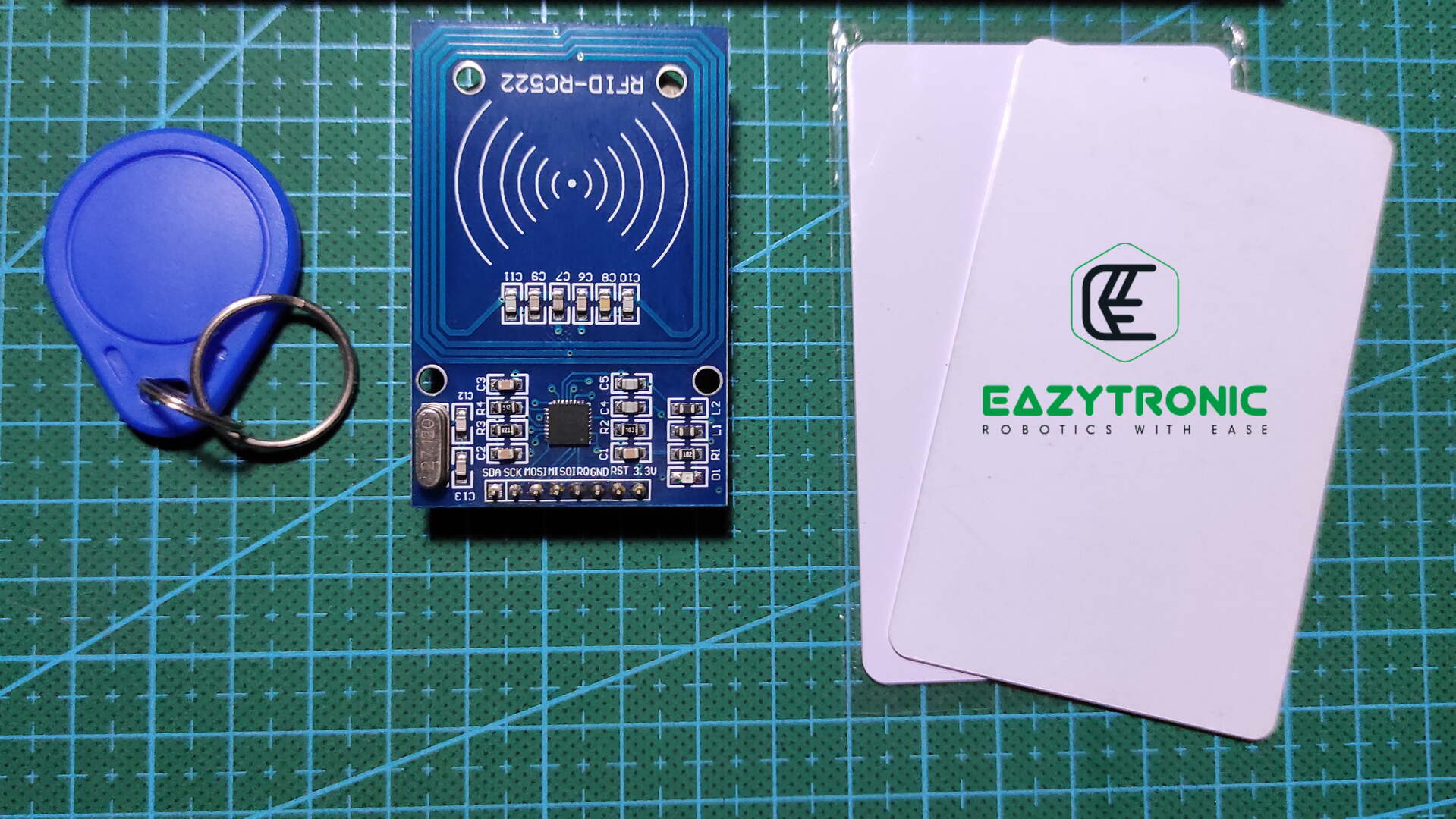
Hello, Friends welcome back, we’re here again with another interesting and very trending topic nowadays i.e., RFID Module. RC522 is the most common and easily available RFID module available in the market. Also, it is widely compatible with most development boards. Many RFID tags and cards are compatible with it, while with this reader only some cards (special) can be read and written completely. This module comes with a tag and card when bought, while the spare can be purchased separately. So let’s dig into the topic.
What is RFID Module?
RFID stands for Radio Frequency Identification, this term nearly defines the working of the RFID Modules. RC522 is one of the most common RFID modules you’ll come through, this RFID Reader is most common among beginners who have learned a few things. Moreover, the compatibility of the Module with various development boards makes it idle for DIY and other uses. However, for professional work like attendance or some other matters you should regard some better security ones.
RFID Modules use radio frequencies for communicating with tags and cards within their periphery. These radio frequencies are specially set for all universal cards of this type and can be operated by any similar reader. While a special Reader requires special frequencies and registered card architecture, this reader MFRC522 requires ISO/IEC 14443 A/MIFARE type tags and cards for communication. Along with this, there are several other types of cards it supports, namely. Mifare1 S50, mifare1 S70 MIFARE Ultralight, mifare Pro, MIFARE DESFire.
RC522 RFID Module, which we’ll demonstrate and explain in today’s article, has a single PCB design that holds both chip and antenna. Antenna term is cliché to say, so we’ll refer to it as coil, as in other readers there is a separate coil for doing so. Apart from this, cards and tags need to be within a specific radius which is slightly less compared to others. Hence, to assure that both card and reader communicate, we need to hold the card steady, within its reading periphery.
RFID tags and cards
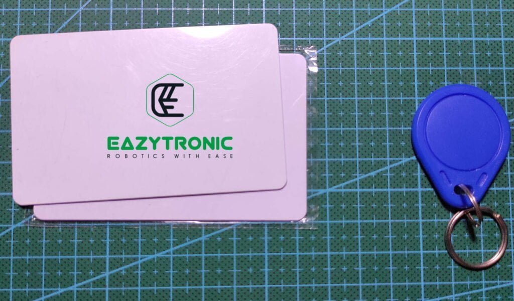
The cards which come along with the module are recommended to use as they are compatible. But if you want to use another, then make sure the radio frequency on which they work matches. Moreover, make sure don’t place cards and readers near strong RF Fields, as these can damage both. Don’t try to make a DIY tag for such a purpose, as there are very few chances of their working. Also, any cloning and re-writing of the data must be done with the most compatible RFID reader.
Advantages
- Easily available at low price, so recommended for beginners.
- Can be hooked up to microcontroller with 3 different protocols
- Logic Level of pins is under the most of the microcontrollers used.
- Adaptive to many types of cards used
Disadvantages
- Repairability of the sensor is next to impossible as the most of the components are SMD.
- Can be affected by other high frequency radio waves in that area.
- No security feature for writing and reading of cards.
Price & Availability
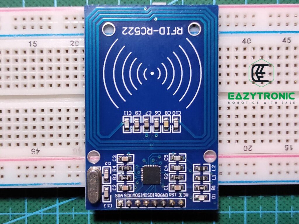
Pinout of RC522 RFID Module

Power & control Pins
3.3V:- This is the positive terminal of the power supply pins. As mentioned, clearly it should be powered with 3.3V for proper functioning. (Within input voltage range)
RST:- This is an INPUT pin with is used to trigger reset and power down of the chip. Power Down is triggered when the pin goes LOW. During power down mode, the oscillator is turned off and input pins are disconnected from all devices. Along with this, internal current sinks are turned off. Reset, triggered with the positive edge.
GND:- This is the power line for the common ground connection.
IRQ:- This is an output interrupt pin which raises an interrupt whenever a card or tag appears within the periphery of the module.
DATA PINS
MISO/SCL/Tx:- This pin act differently in different modes. When SPI is enabled, this pin act as MISO – Master In Slave Out. This act as input pin which receives the data (from the device connected to SPI port. In I2C mode this pin act as SCL—Serial Clock which generates synchronize signal for transmission of data through SDA pin. Lastly, in UART/Serial communication this pin act as Tx which transmits bits of data to the Rx pin of the other device.
MOSI:- This pin is used when the module is configures in SPI Mode. It receives the data from the microcontroller, to the device connected on the other end or in multiple connection formation.
SCK:- This pin receives the clock signal from the microcontroller and according to this data is exchanged through SPI port.
SDA/SS/Rx:- Like previously, this pin act differently in different modes. In SPI mode, this pin act as SS-Slave/Chip Select. This pin selects the device when connected in multiple device formations. Furthermore, in I2C communication it acts as SDA-Serial Data, it transfers the data to & from the microcontroller. In UART/Serial communication this pin act as Rx which receives the data from the microcontroller bit by bit.
Specifications of RFID Module
| Operating Voltage | 2.5V – 3.3V |
| Operating current | 13mA-26mA |
| Idle Current | 10mA-13mA |
| Operating Frequency | 13.56MHz |
| Card Reading Distance | 0-60mm |
| Data Transfer Rate | 10Mbits |
| Protocol | SPI (preferred) |
| Dimension | 60mmx40mm |
Schematic
Above is the schematic of the RC522 RFID Module, it is generated using information available on the internet and reverse engineering an actual Module. Though the schematic is tested, it is still not recommended replicating one using this, as there is no knowledge about the NFC coil. Furthermore, most of the sensors including the main chip is SMD version which is very hard to solder for beginners. Hence, replacement of the sensor parts if something is worn out is not an easy task, as the spare components are hard to find.
Now for the main chip, i.e., MFRC522, which is a specially designed chip for reading and writing contactless cards and tags of a specific type. What’s more, well apart from it being specifically designed, this also works on a specific Radio frequency which needs to be matched with the card or tag to become functional. Briefly, a card can only be read and written by its respective type reader or writer, else it will damage the data inside the tag or read incorrect data. Along with this, other factors may affect its working, which is discussed in the working section.
In addition to all, there are many other components which are used to make a complete Module. Like in above schematic, there you can see a 27.12MHz Crystal oscillator which is used to generate a timer cycle. As a result, this is the double the frequency of the Electromagnetic field generated by the chip. In simple words, this crystal oscillator is used to provide the timer signal to generate the electromagnetic field of half of its original value for communicating.
Working
Now let’s see the working of the complete Module, Its working is somewhat complicated but once understand can be retained more easily. Firstly, the main chip MFRC522, as mentioned earlier it is a specially designed which is used to read and write data to and from specific type cards and tags. For detailed information about this IC, you can refer to its datasheet attached below.
Although the Module can be configured using any one of the 3 mentioned ways, the most common or adapted one is SPI communication. In this communication, 4 power pins are used in addition to the power lines, IRQ pin is optional and can be used for other instances or interrupts. MISO, MOSI, SS & SCK are the pins that need to be connected to the SPI port of the microcontroller for the trans-communication of data. However, you have to make sure the microcontroller you are using is of the same logic level as that of the Module, else it can cause certain problems.
For this issue, you can use a logic level shifter, which is very easily available. I recommend this because overvoltage signals can damage your module, and I hope you don’t want that. MFRC522 continuously generates Electromagnetic Field (Radio Waves)of 13.56MHz, which is the communicating frequency (medium). The IC remains in idle state until a tag comes in contact with the electromagnetic field emitted by the module’s coil.
Reading/Writing
Foremost, the module continuously emits the electromagnetic waves which covers a height of 60 mm in equipotential surfaces. The IC remains in idle state without any disturbance in the electromagnetic field. As soon as a card or tag enter the em waves region, IC an interrupt signal which can be read on the IRQ pin. Moreover, it also gives the signal to IC, making it clear that there is some card or tag.
Whenever a card comes in contact with this electromagnetic field, they become active. As cards and tags have no power source, they induce EMF/potential difference/voltage with this electromagnetic field and generates a counter electromagnetic field in that region. This disturbance in magnetic field is identified by the IC, and the coil starts receiving fluctuations in the counter electromagnetic field. This method is called back scattering. Cards or tags have a special chip which doesn’t do much work. They just runs on the voltage induces by the coil embedded into them.
As soon as the chip in them becomes active, it starts generating the counter em waves which represent the data stored in them. These fluctuations are then received by the reader and decoded into the exact data in human-readable form. During the time when the data is being transferred, reader doesn’t emit waves, rather read them as it has to decode these waves onto data. Certainly, there is enough power for the card to transmit the complete data. There are certain hashes which indicates the start and ending of data, incomplete or insufficient data results in error.
Finally, we have to sum up the article, I hope you like the explanation. If you find this insufficient then comment below, I’ll try to gather more information and update it soon.
FAQ
Q. What is the input voltage range and Logic level of the RC522 RFID Module?
RC522 RFID Module can work between 2.5V -3.3V, however the input pins are upto 5V tolerant, so you can easily connect them to respective microcontrollers.
Q. What type of communication is used to connect RC522 RFID Module to microcontroller?
You can use any of the mentioned protocols, however the most preferred one is SPI, so I recommend you to use it.
Q. Can other radio waves disturb the transmission process of the RC522 RFID Module and Cards?
Yes, other high frequency waves like Wi-Fi Router placed near module and other such devices can interfere in the transmission process and can affect them.
Q. Can we use two or more cards at the same time for reading and writing with RC522 RFID Module?
You can try so, but in some cases this results in messing up the data, So I wouldn’t recommend it.