
Hey guys, I’m back with a flame sensor with Arduino, and another easy-to-use sensor with Arduino. This sensor is similar to the IR sensor with Arduino I demonstrated in the previous article. Although this sensor is different from the IR sensor, its working is similar to the IR sensor you’ll understand further. This sensor is mainly used for detecting fire or a large source of heat. As the sensor only detects the IR light, therefore certain precautions and exceptions must be taken care of in mind. Let’s proceed further.
Flame Sensor & Arduino in Brief
Flame Sensor
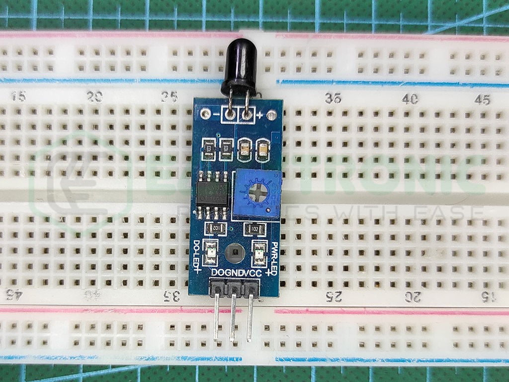
It is one of the important sensors that need to be practiced to see more advanced sensors. This sensor has almost the same components from the IR Sensor. The difference is the removal of certain components for the sensor to work differently. However, it is not advised to remove any component from the IR Sensor to do so without any schematic knowledge.
The sensor is built around LM393 IC, which is a Low Voltage Offset Dual Comparator. This IC compares the voltage on the Inverting and Non-Inverting terminals of a comparator and gives the output accordingly. Hence, we only use one comparator and don’t need the other one.
Flame sensors can be used with any microcontroller, as it supports both 3.3V and 5V power inputs. Also, the logic level is completely dependent on the input level, so you don’t have to worry about converting it. But the sensor only gives digital output, as there is no use of an Analog signal in this case.
Lastly, there are some drawbacks of the sensor, like it can not be used in direct sunlight. As sunlight also emits high amounts of heatwaves in the form of IR Radiation, the sensor may interpret them as those coming from a large fire. Resulting in the wrong detection. The detection range and intensity can be controlled via the onboard potentiometer.
Arduino UNO
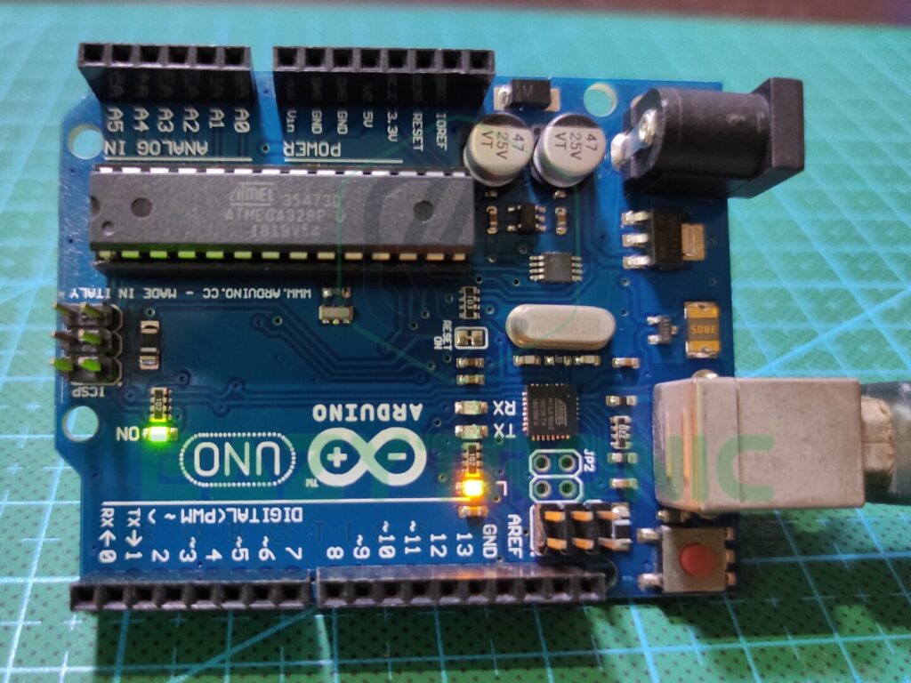
This is one of the recommended microcontroller boards in the market that is available at a cheap price. This board is easily available in both online and offline markets at an affordable price. Under this price point, it offers many useful features that make a complete package for a beginner. Also, it offers more durability than most of the boards out there.
Arduino UNO is made out of an ATMEGA328PU microcontroller that comes in a DIP-28 package. As most of the components on this board are in the DIP package. This makes it more repairable in case of faults in the board. The ATMEGA328PU is an AVR-Based 8-bit CMOS microcontroller that can run at 16MHz clock speed. What’s more, is that you can even program this IC via FTDI programmer separately also.
The Board provides sufficient storage and memory for all types of code to run. It is packed with 2 KB of SRAM and 32 KB of programmable flash memory, which is sufficient for even some big projects. More importantly, this configuration of best for experiments due to the low cost of the board. It also packs within itself 1 KB of EEPROM that can store data permanently, even after a new code upload.
Arduino UNO comes with a sufficient number of pins. It has a total of 23 I/O pins that can control lots of devices. This includes 13 digital pins, consisting of 6 PWM pins within them. Along with this, it also provides 6 Analog pins with a resolution of 10-bit, which is very good at a beginner level. Moreover, it provides both types of power supply 3.3V and 5V with some other pin for miscellaneous things.
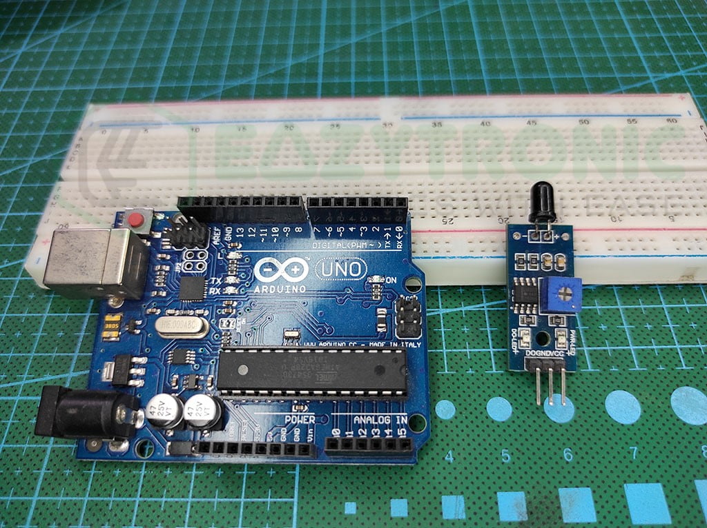
Material Required
- Arduino UNO
- Flame Sensor
- Breadboard
- Jumper Wires
- A matchbox or lighter for a fire source (in the presence of an adult).
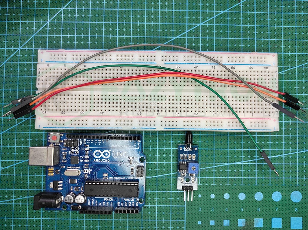
Fritzing Schematic
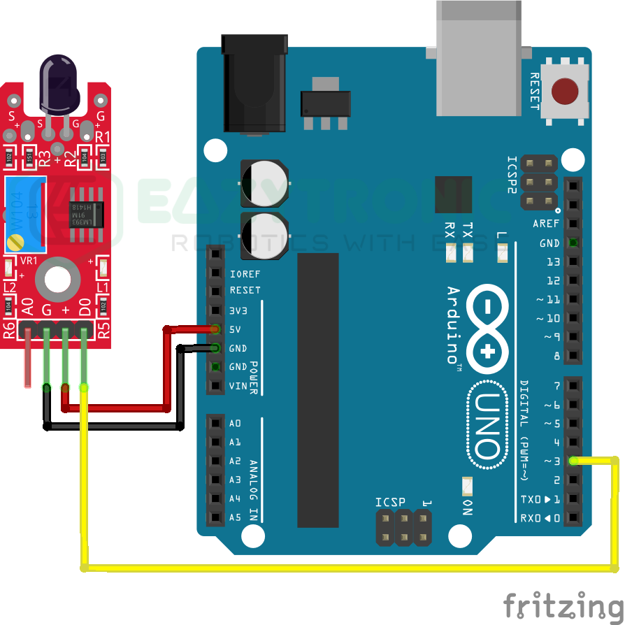
Wiring
| Arduino UNO | Flame Sensor |
|---|---|
| 5V | Vcc/+ |
| GND | GND/- |
| D3 | D0/DOUT |
Programming Arduino
One of the important sections of the article is to prepare the system to program the Arduino UNO. Once you have completed all the steps mentioned in the previous steps, you can proceed further. If you are a beginner, then you must first download the Arduino IDE from the official website. Next, make sure to install all the board definitions and libraries. If you are an experienced user, you must have prepared this in advance. However, for a complete, detailed explanation of the IDE & various boards of the Arduino Series. For this, make sure to read the introductory article here.
Code
Below is the code for the Flame sensor with Arduino UNO. As we’re going to use only Digital output, the code is for that only. However, I have not seen and laid my hand on any different version of the Flame sensor. Therefore, there is no surety that this code will work on all sensors.
#define Flame 3
#define LED 13

 void setup(){
   pinMode(Flame, INPUT);
   pinMode(LED, OUTPUT);
 }

 void loop(){
   if(digitalRead(Flame==HIGH){
     digitalWrite(LED, HIGH);
   }
   else{
     digitalWrite(LED, LOW);
   }
 }
The above code uses a simple condition, just as in the case of the IR sensor with Arduino UNO. You can use the same code if you have read that article. Anyways, make sure to save the code with “flame_sensor_arduino.ino” or any other name, but no white spaces are allowed in the name.
Explanation
The explanation part is more or less similar to the IR sensor, so there is no need to proceed if you have already read the IR Sensor with Arduino UNO Article.
First, we define the pins for the Flame sensor and LED, which will be used to display the sensor’s condition. We will be using a digital pin because we are now using the flame sensor’s digital output. While, we will be using the on-board LED for the LED.
#define Flame 3
#define LED 13
You can change the pin on which the Flame Sensor is connected but make sure to change the same in the schematic. Also, instead of using the int variable to store the pin for the flame sensor, I have used the define macro argument. You can search for this if you have any doubts.
void setup()
void setup(){
   pinMode(Flame, INPUT);
   pinMode(LED, OUTPUT);
 }
We must provide the pin type we chose for the Flame Sensor and LED in the setup section. Apart from that, there is no need for us to initiate any communication because we are employing straightforward I/O functionality. The LED will also be utilized to show the Flame Sensor’s condition.
The Sensor pin’s pin mode is defined as INPUT in the first line and remains the same in both versions. We’ll also be using the OUTPUT pin type for LED. However, you can include the lines necessary to start such a connection if you’re using a display to show the output. I’ve already shown you how to interface various screens here.
void loop()
void loop(){
   if(digitalRead(Flame==HIGH){
     digitalWrite(LED, HIGH);
   }
   else{
     digitalWrite(LED, LOW);
   }
 }
The core code is located here, in the loop section. Flame Sensor is simple to use, therefore there won’t be much code to do only to display the IR Sensor’s state. We begin by examining the IR Sensor’s state from the first line. We determine whether the sensor’s output is HIGH or LOW. The version of the Flame Sensor has a significant impact on both the output and the condition.
As told earlier, I haven’t experienced any different model of this sensor unlike the Ir Sensor, so I can’t solve any issues regarding this. However, if you have any issues, write them down in the comment below, I’ll solve them.
With this, we end our demonstration of Flame Sensor with Arduino UNO.