
Hello guys, we’re back with GC9A01 with Arduino, another interesting article in the Arduino Series. In today’s article, we’ll be discussing interfacing the GC9A01 display with Arduino UNO. GC9A01 is another interesting display just like ST7789. I have recently completed the interfacing of ST7789 with Arduino UNO, make sure to read it for reference. This display comes in a round/circular shape that makes it different from the ST7789 display. Moreover, there is a change in driver IC and thus a new library and functions. To more about it, let’s begin.
GC9A01 and Arduino in brief
GC9A01
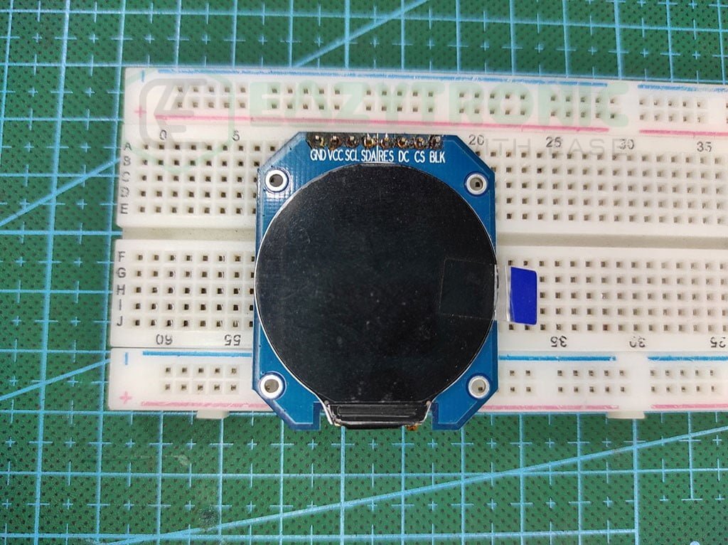
It is another fascinating display, like ST7789. Certainly, there are some differences between the two that I’ll be explaining further. It is a 1.28” display that comes in a resolution of 240×240. Yes, it is the same as the ST7789, but in a different shape.
This display comes in a circular shape, so it’ll be precise to say that it has a radius of 1.28”. Therefore, it is most commonly seen to be used in small form factor devices or wearables like smartwatches. This is also because it has a fast refresh rate that makes it ideal for displaying dynamic content and animations. In some versions, the display is also available in the touch variant.
Like ST7789, this display also supports SPI communication, which makes it useable with many development boards. Moreover, this display also works on a 3.3V logic level, which means you need to either consider this or use a logic-level converter for data lines.
The driver used in the display is GC9A01, which also gives the name to the display and makes it popular. However, the model/variant of display available in the market cannot be all same. Therefore, certain versions work flawlessly.
However, the version I’m using is the simple one, as I was not able to make the other version of the display work. Hence, upon certain suggestions from other people, I ordered the one that resembles the pieces from AliExpress or the simple one. Hopefully, that works and I recommend you the version the same as mine.
Arduino UNO
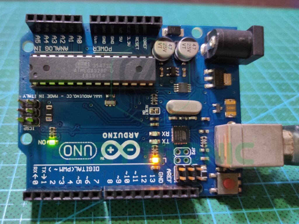
Arduino UNO is one of the most common and demanding microcontrollers in the market. Not only it is popular among beginners but also for testing purposes, it is used by professionals and hobbyists. This board is available at low prices in both online and offline markets also the components of the board can be easily found.
UNO board is built around ATMEGA328PU, which comes in a DIP-28 package, making it easier to replace the main IC if something goes wrong. ATMEGA328PU is an AVR Based 8-bit CMOS microcontroller that operates at a frequency of 16MHz. Although this sapped is quite low as compared to other boards at the slightly high price range, but anyway, it works well as per beginner’s view.
ATMEGA328PU microcontroller contains 2 KB of SRAM, which is sufficient for most of the code to run. Moreover, it is paired with 32 KB of programmable flash memory. Also, it encloses 1 KB of EEPROM that can be very useful in projects like Home Security. Next, there are sufficient pins available on the UNO board. This includes 13 digital pins and 6 analog pins.
Along with some additional pins, the total number reaches 23 I/O pins available on the Arduino UNO Board. Among the 13 digital pins, it includes 6 PWM pins and other data pins like SPI and Serial. However, the Serial communication is busy during the code uploading to the board. The I2C communication is avail be at the A4 & A5 pins of the analog Pin section. For more detailed information regarding Arduino, refer to the Arduino Introductory article.
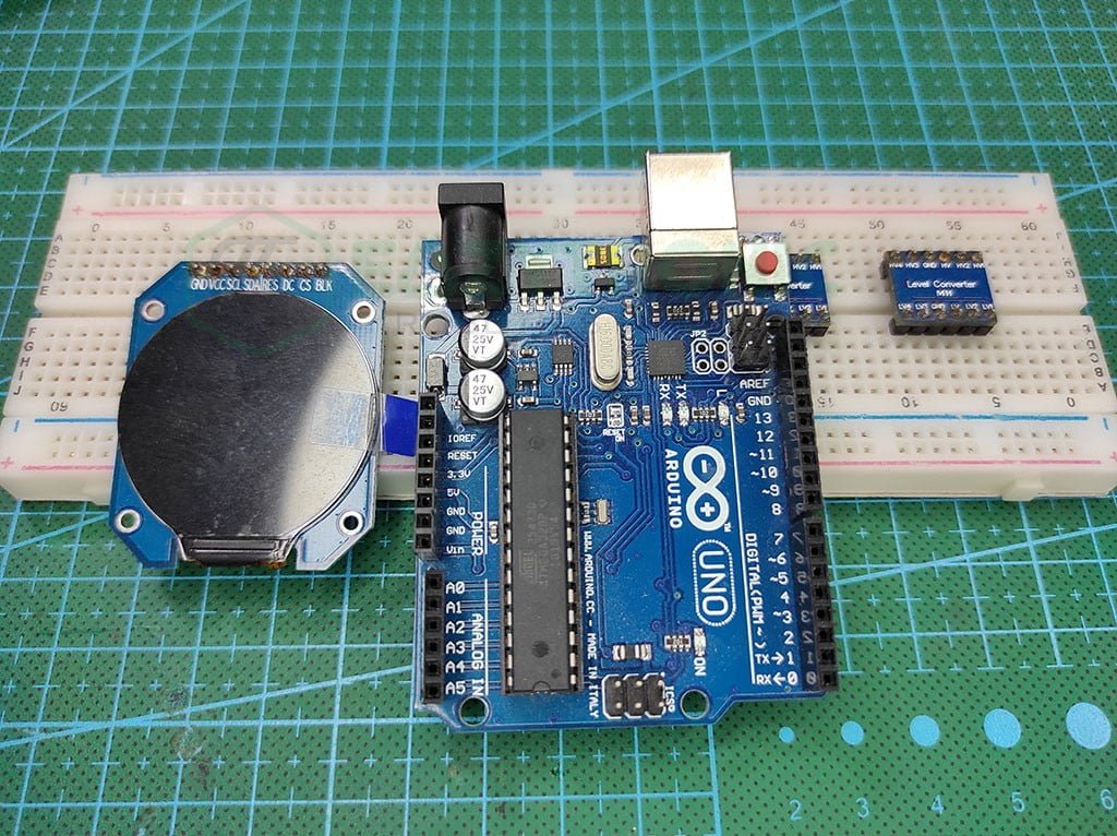
Material Required
- Arduino UNO
- GC9A01 display
- A logic level converter
- Breadboard
- Jumper Wires
- A system to program Arduino
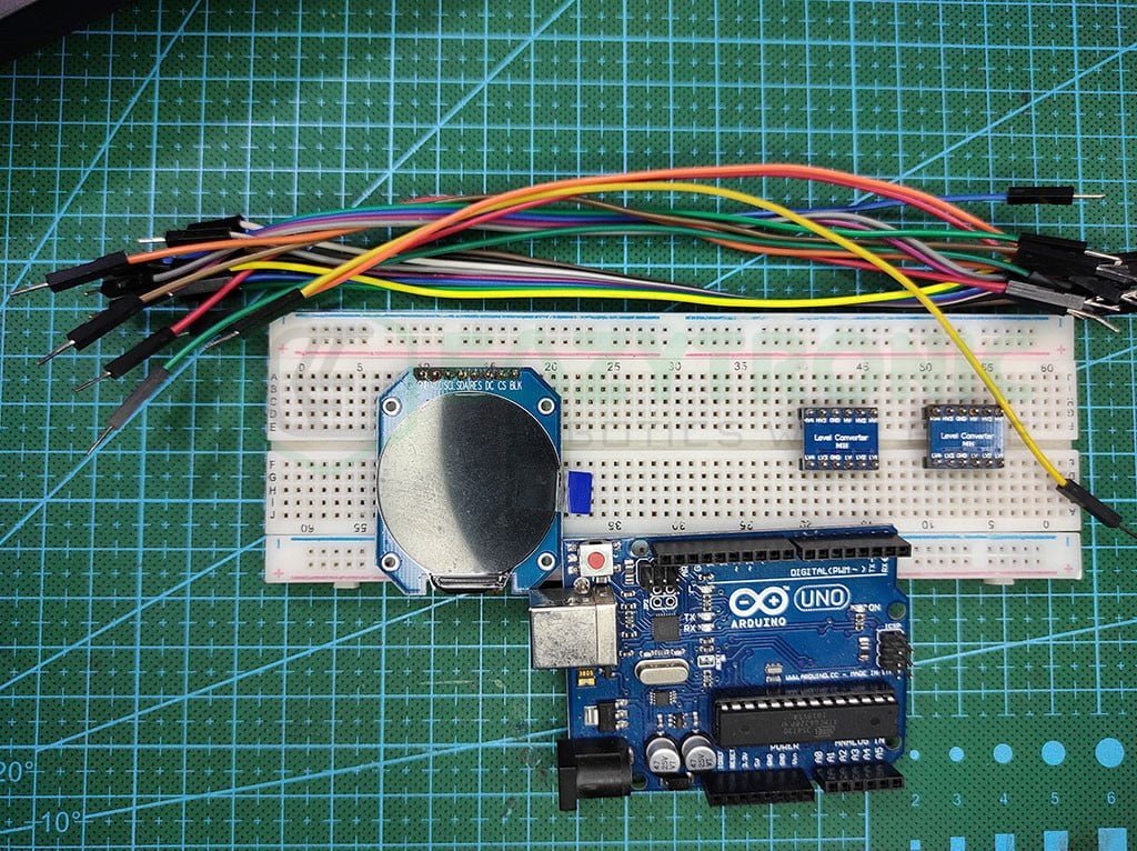
Fritzing Schematic
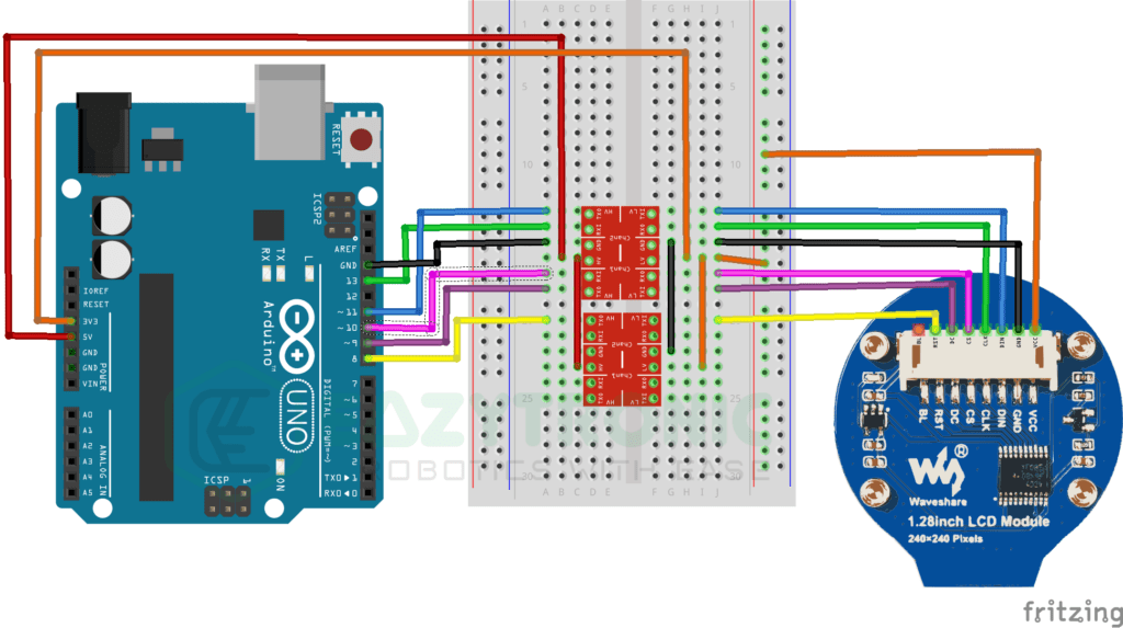
Wiring
| Arduino UNO | LOGIC LEVEL CONVERTER |
|---|---|
| 5V | HV |
| 3.3V | LV |
| GND | GND |
| D13 | HV1 |
| D11 | HV2 |
| D10 | HV3 |
| D9 | HV4 |
| D8 | HV5/HV1(2) |
| LOGIC LEVEL CONVERTER | GC9A01 |
|---|---|
| LV | Vcc |
| GND | GND |
| LV1 | SCL/CLK |
| LV2 | SDA/DIN |
| LV3 | CS |
| LV4 | DC |
| LV5/LV1(2) | RST |
NOTE:- As explained earlier, GC9A01 Display only works at a 3.3V logic level. Therefore, to be on the safer side, I have used a LOGIC LEVEL CONVERTER. I have used 2 pieces having 4 channels each, but you can use 1 with 8 channels.
Programming Arduino UNO
Programming Arduino UNO is the next step in the demonstration of the GC9A01 with Arduino. Further, I’ll be giving code along with line by line explanation of the code. But before this, as always, make sure that you have downloaded and updated the Arduino IDE. Also, make sure to update all the board and library definitions so that there is no error during compilation. Moreover, if you are new to Arduino IDE, then make sure to read the introductory article on Arduino. This will give an overview of Arduino and its different boards. With this, let’s start.
Installing Library
Once you have done all the checks above, then we can continue to test the code. But before that, there is a small thing that we have to do so that we can use the display. If we talk about the code, then it’ll be similar to the code in the ST7789 with Arduino. The code works on the display version available to me, but on some others, this doesn’t work. Therefore, I cannot guarantee that the code doesn’t work on such displays.
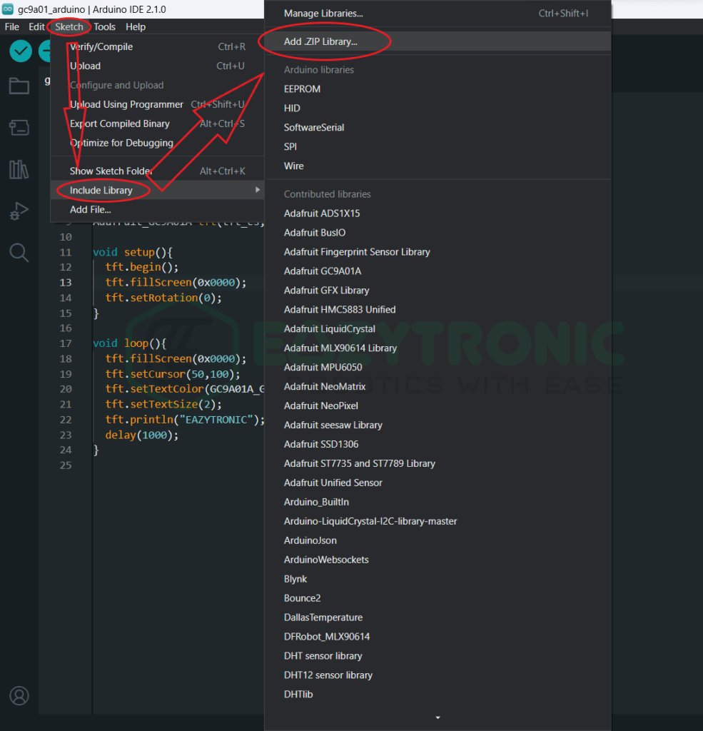
However, if you want me to use the display and adjust the code according, I’ll give it a second try and try to make the work on the code for that. For this comment down & I’ll moderate it. So to install the Library, you can use the inbuilt Library manager of the Arduino IDE if you found any compatible library there. However, the two libraries I use most often are one from Adafruit and the other from some other author.
The links to both libraries are as follows: Adafruit GC9A01, and GC9A01. Both libraries work for me, so you can use any one of them, however, the easiest one to use is the Adafruit one. Although in future you may come through some errors for some board. Download the zip file for both libraries and install them as shown below.
Code
Now is the time to write the code, the code is simple and similar to the ST7789 display. Also, if you are using the Adafruit library, then most of the function used with the ST7789 display is similar. However, it is always advised to visit the GitHub page of the library to get an overview of all the functions in the library.
#include "SPI.h"
#include "Adafruit_GFX.h"
#include "Adafruit_GC9A01A.h"

#define tft_cs 10
#define tft_dc 9
#define tft_rst 8

Adafruit_GC9A01A tft(tft_cs,tft_dc,tft_rst);

void setup(){
  tft.begin();
  tft.fillScreen(0x0000);
  tft.setRotation(0);
}

void loop(){
  tft.fillScreen(0x0000);
  tft.setCursor(50,100);
  tft.setTextColor(GC9A01A_GREEN);
  tft.setTextSize(2);
  tft.println("EAZYTRONIC");
  delay(1000);
}
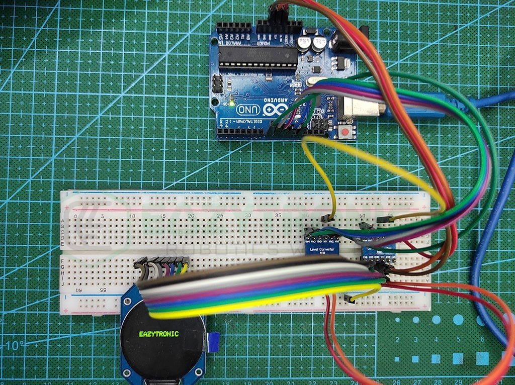
The above code works well with the display version available to me. Also, the function of the library are similar, so there is less confusion. As mentioned above, the code works perfectly because I have used the logic level converter and the correct model of display. If either of these things is an issue, then make sure to check it. If you are using the old-school method of using the resistor, then maybe there’ll be some issues in large codes. Lastly, save the code with something relatable name, the one I suggest is ‘gc9a01_arduino.ino‘.
Explanation
This section is most important as it explains each line of code given above. Make sure to pay attention to the explanation so that later you can edit the code accordingly. However, if you have read the ST7789 article, then you might have an idea of the lines used in the code. Anyway, let’s start with the explanation part.
#include "SPI.h"
#include "Adafruit_GFX.h"
#include "Adafruit_GC9A01A.h"
In the beginning, we include some libraries that are needed for the code to compile. Make sure you install the Adafruit GFX library if you are using this display for the first time. The Arduino GFX library is the main library for performing all operations further in the code. Along with this, we also include the ‘SPI.h‘ library that enables the SPI communication between Arduino UNO and GC9A01 display. The library for GC9A01 is not available via the in-built library manager, therefore you have to download and install it manually.
#define tft_cs 10
#define tft_dc 9
#define tft_rst 8

Adafruit_GC9A01A tft(tft_cs,tft_dc,tft_rst);
Next, we define some variables to store the pin for connecting the excess pins of the display. Although I didn’t recommend using this as it utilizes the memory of any development board, instead you can just use the pin in the line followed by the first three lines. Further, we define a variable/object that points to the display we have connected. From now, we’ll be using this variable to perform all the operations on the display. Make sure to assign the pins correctly, or else the display won’t work. Moreover, the reset pin is connected to the board reset pin by default. Therefore, if you want to connect it to some other pin, then change the number.
void setup()
void setup(){
  tft.begin();
  tft.fillScreen(0x0000);
  tft.setRotation(0);
}
Now comes the setup section, in this we define the statements that need to be executed only once. Hence, it contains a few lines of code that need to start a communication or something similar to this. In the first line, we start the communication with the display. As the Arduino runs on 16Mhz that implies the SPI frequency will be half of it i.e., 8MHz so there is no means of setting a custom SPI speed.
However, while using the ESP32 and NodeMCU or STM32 board, I intentionally set the speed to the maximum so that the display runs at maximum speed. In the next line, we clear the display for any past operations stored in its registers. Finally, like the ST7789, I rotate the screen to the desired position by using the statement, <variable>.setRotation(0-3). The range of the rotation is 0-3 which corresponds to the 4 quadrants in the coordinate plane.
void loop()
void loop(){
  tft.fillScreen(0x0000);
  tft.setCursor(50,100);
  tft.setTextColor(GC9A01A_GREEN);
  tft.setTextSize(2);
  tft.println("EAZYTRONIC");
  delay(1000);
}
Lat is the loop section of the code. This section plays a major role as this will be repeated again and again continuously. At the beginning of the code, we fill the screen with a BLACK(0×0000) color. This will clear the display. Next, we set the cursor of the display to the desired position referred to as (x, y).
While drawing anything or positing the cursor, make sure to keep in mind that the display is of the radius 1.28”. If you misplace the characters, without taking this into regard, you may see your object cutting from the sides. Further, we change the color of the text we’ll write on the display.
Moreover, I also change the size of the text to something visible more clearly. The size of the text depends on the font file you’re using. However, I prefer to use the default one first before any new font file to make sure that the code works and has enough space.
At last, we print the text on the screen and give a 1-second delay to make the difference visible. This loop will run continuously without any error on the display available to me. However, some displays might not respond as they might need a different SPI_MODE to start. You can also change the speed of the display while initializing to change the animation speed also.
With this, we’re done with GC9A01 with Arduino UNO article. I hope you find this interesting and enjoy it. If you find any issue regarding this, then make sure to comment down below. I’ll resolve it ASAP.