
He friends, we’re back with Interfacing LCD with Arduino via I2C module. LCD module is one of the most important modules that a user needs to display something. Although there are many other types of displays nowadays, the very basic one is the Liquid Crystal Type. We have also demonstrated how to use this display in 4-bit mode, but that mode uses more pins as compared to the I2C connection. However, if you want to read that article, you can visit it from LCD 4bit mode. Via using the I2C module we can connect LCD to also any microcontroller like ATTINY45 as it can support I2C connection. With this, let’s begin today’s discussion.
Arduino and I2C LCD in brief
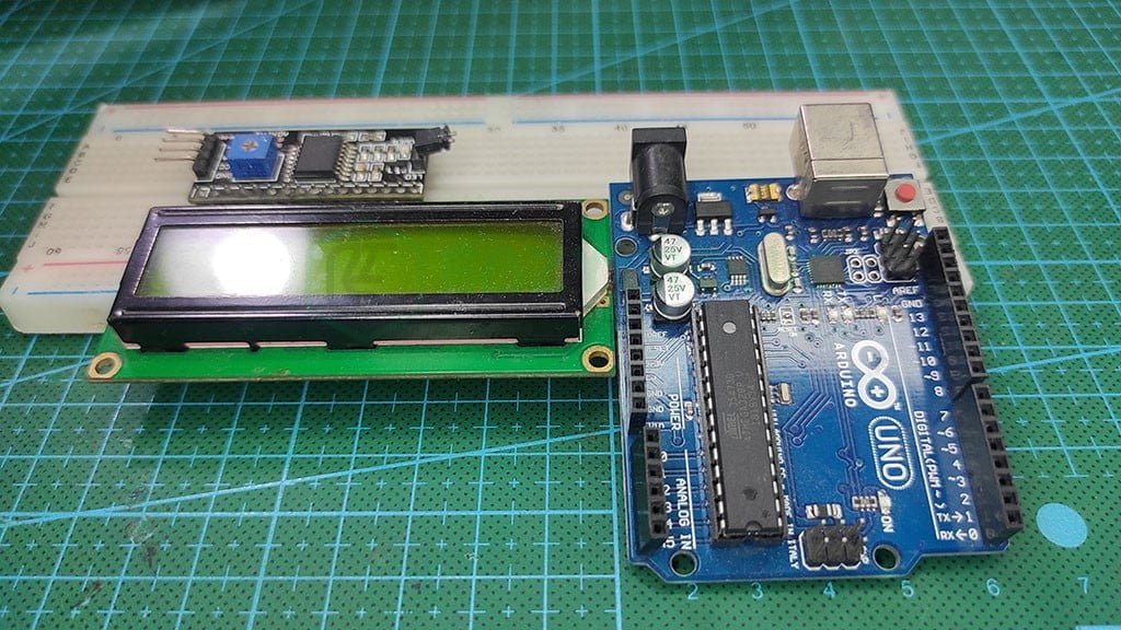
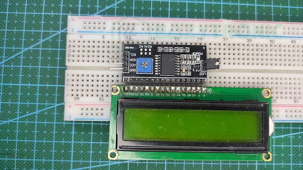
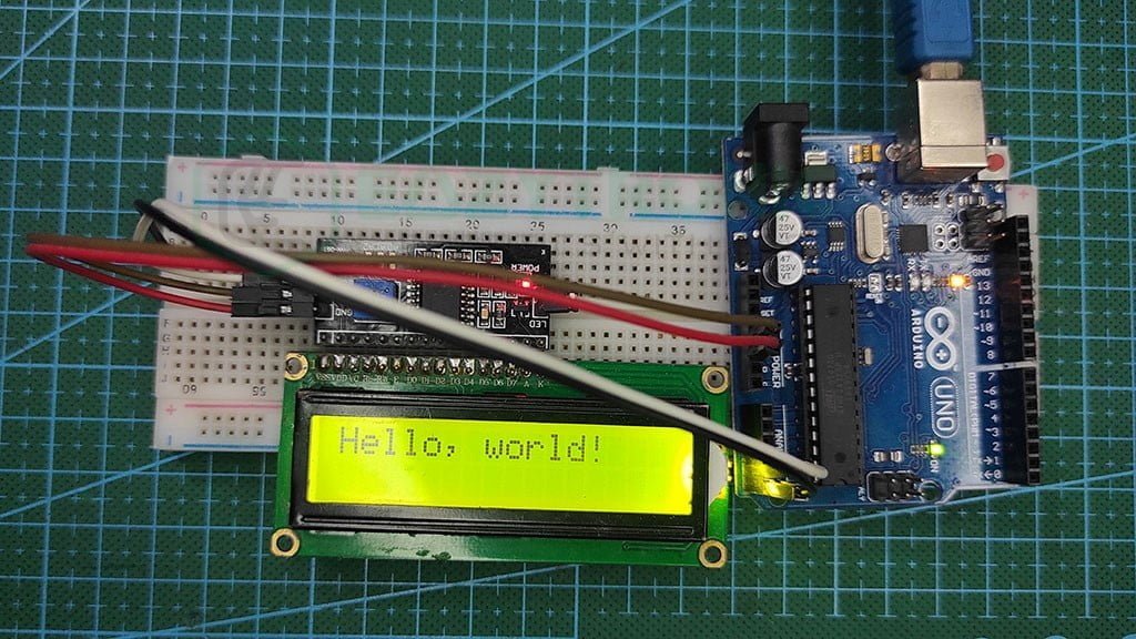
I2C Module with LCD
Liquid Crystal Display aka LCD is one of the important modules in the electronics field. As this is the most basic module to display something or give an output that can be easily understood by a human. In simple words, this is the most basic visual output device that can be used with any microcontroller. Most of you have seen this type of display in many places like 3D printers, CNC machines, and many other big types of machinery used in factories. As this display uses the most common 4-Bit mode, therefore it can be used by an old microcontroller like 8051 also. However, today we’re going to use LCD with Arduino UNO via an I2C module.
The I2C module is a crucial attachment that has been developed for I2C displays. Although, this module makes the display look bulkier. But this makes it easy to write the code as there are fewer lines of code. Moreover, the pins used in connecting the LCD to any microcontroller to 2. Although this module eases some difficulties, it adds a separate library for the module to compile the code. In addition to this, If there is any fault in the module you cannot repair it easily as the components are mostly SMD. So it is advised to have a spare I2C module in advance in case you accidentally fry one so that you can replace it.
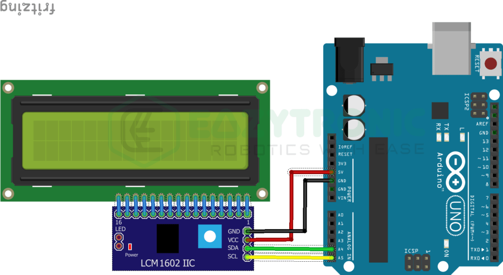
Now comes to the connection part, the I2C module takes the I2C input from the microcontroller. Further, it converts that signal into the 4-bit or 8-bit mode as per the user command. However, I myself use the 4-bit mode as it is more familiar to me than the 8-bit mode.
Arduino UNO
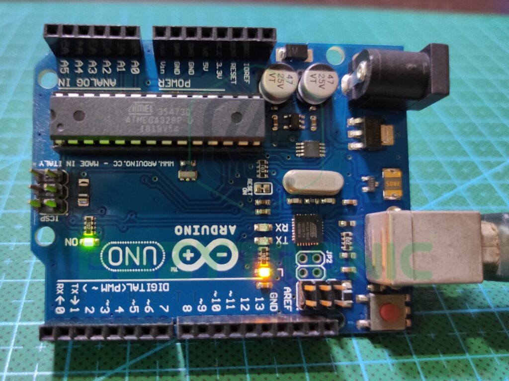
One of the most well-known and popular microcontrollers most of you start with is the Arduino UNO. This is because it is the most beginner-friendly version of the Arduino board, in addition to the fact that it is inexpensive. Moreover, it is the only variation of the Arduino Board whose primary IC is easily replaceable. This board may be readily fixed if there is any damage caused by the main IC, unlike the Arduino Mega, Nano, Pro mini, and micro. The ATMEGA328PU IC, which has DIP-28 packaging, serves as the foundation of the Arduino UNO. Also, it is the same IC that can be found in some SMD versions of the Arduino UNO. But comes in a different package, as some of you may already have. AVR-based ATMEGA328PU is an 8-bit CMOS microprocessor with a 16MHz operating frequency.
It has 23 programmable I/O pins, practically it includes all of which are necessary for a microcontroller to have. There are 6 PWM pins and 13 digital pins total, of which 2 can function at a high frequency of around 980Hz. Moreover, it includes 6,10-bit resolution analog ports. It features 32 KB of programmable flash memory and 2 KB of SRAM. In addition to this, it also has an EEPROM memory of 1 KB in which you can store data, even after the board resets. Overall, it includes all the necessary communication that a microcontroller must have. Along with Serial communication, it is a full-packed microcontroller for beginners. If we talk about power delivery, then it can deliver both 5V and 3.3V with adequate supply for seniors.
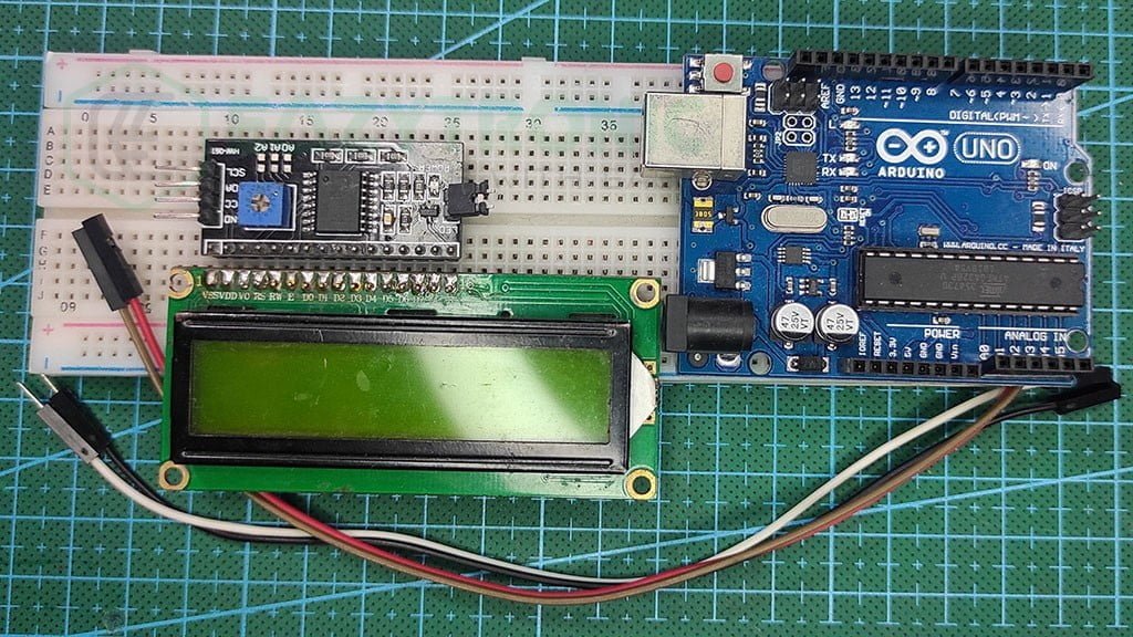
Material Required
The material used in the demonstration of LCD with Arduino is easily available in both online and offline market. The model of the devices and sensor may vary according to your area. However, the working will remain the same.
- Arduino UNO
- LCD
- I2C module
- Breadboard
- Jumper Wires
- A system to program Arduino.
Fritizing schematic
Programming Arduino UNO
Here comes the important section of the article. Before proceeding, make sure you have downloaded the Arduino IDE and updated it to the latest version. Also, make sure to update all the Board definitions and libraries so that there will be no errors in the compilation. Besides, if you are new to Arduino microcontroller, then make sure to read the Arduino IDE introductory article for a more in-depth understanding.
Installing Library
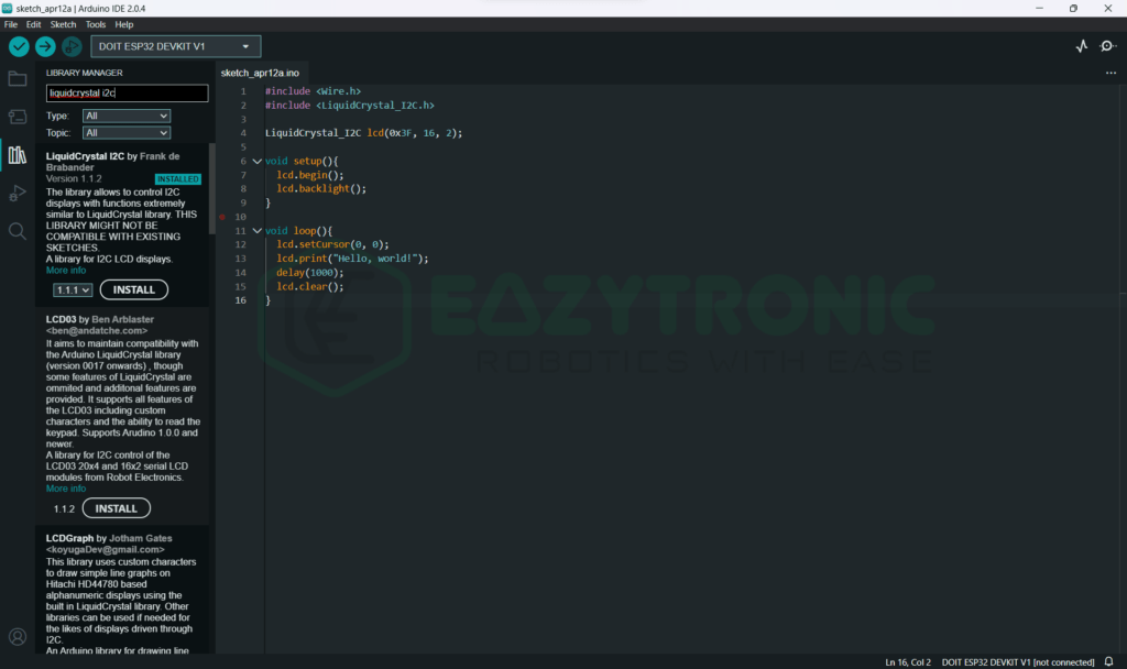
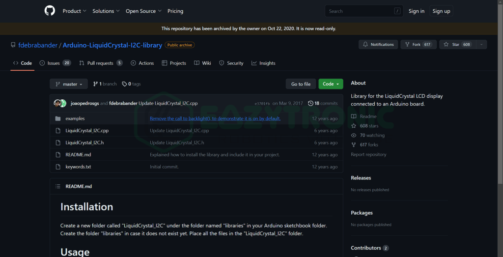
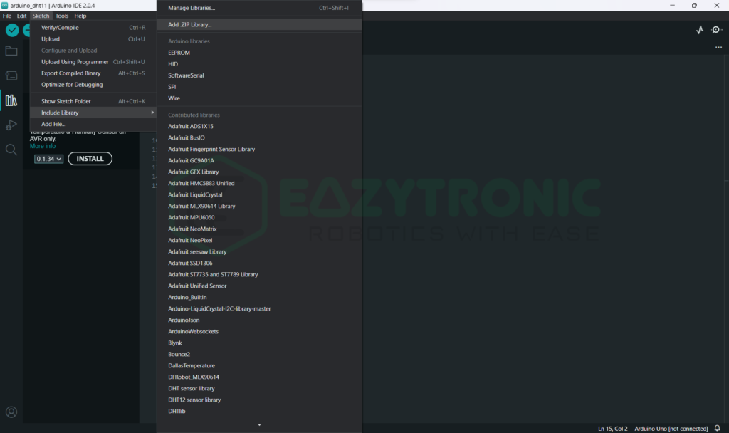
Once you have completed all the necessary steps now you can install the library for the I2C module to work with a 16 × 2 LCD Display. There are many Liquid Crystal I2C libraries available on the internet, you can download any and use them. However, the one I’m using is easy to use and contains very simple functions. Hence, it is very rare you feel any difficulty using it. You can download the library from the inbuilt library menu of the Arduino IDE. To install the Library, you can choose the Add zip library under the Sketch menu > Include Library > Add . ZIP Library. I have also attached images for reference.
Code
Below is the code for the 16 × 2 LCD with Arduino via I2C Module. Some things need to be made clear that’ll be explained in the explanation section of the article.
#include <Wire.h>
#include <LiquidCrystal_I2C.h>

LiquidCrystal_I2C lcd(0x3F, 16, 2);

void setup(){
	lcd.begin();
	lcd.backlight();
}

void loop(){
  lcd.setCursor(0, 0);
  lcd.print("Hello, world!");
  delay(1000);
  lcd.clear();
}
You can save the code with any name, but I advise you to save it with some meaningful name that you can remember easily. I have saved the code with lcd_i2c.ino, you can also use this name.
Explanation
This is another important section of the article where I’ll explain the code line by line. The code is completely working and doesn’t show any errors. However, to completely unlock the functioning of the library, you should read all the functions of the library on the GitHub page. With this, let’s begin our explanations.
#include <Wire.h>
#include <LiquidCrystal_I2C.h>
In the first two lines, we import two essential libraries for the code to compile. Wire.h library is used to enable I2C communication and LiquidCrystal_I2C.h library enables the use of an I2C module with a 16 × 2 LCD. If you haven’t installed any of the two libraries or if there are 2 or more identical versions of the library, then it might show an error. Therefore, make sure to install only one version of the library and if it shows any error then make sure to check for same/similar repositories.
LiquidCrystal_I2C lcd(0x3F, 16, 2);In the next line, we create an lcd variable/object that corresponds to the I2C module we have connected. It is the further used for all operation regarding LCD further. The syntax of this line is as follows, LiquidCrystal_I2C <variable object>(<I2C Module Address>, 16, 2); The variable object name, and its address must be accurate else the code will not work. If you don’t know the Module I2C Address, then scroll down to last section for details.
void setup()
void setup(){
	lcd.begin();
	lcd.backlight();
}
This is the main loop that runs only once, therefore only the code that we need to run once will be written here. First, we begin the I2C communication via I2C at the address defined by us above. If you have connected multiple display then make sure to use the correct one as any incorrect address can change your whole code or other display. Next, we turn the backlight on by <object>.lcd() line. You can also trim the brightness of the lcd via the onboard potentiometer, just like the 4-bit mode connection.
void loop()
void loop(){
  lcd.setCursor(0, 0);
  lcd.print("Hello, world!");
  delay(1000);
  lcd.clear();
}
Last, we have the loop section of the code that runs continuously without any interruption until any error occurs. Once we have begin the communication, next we have to print something on the display. In order to make sure that the display is working well via I2C module communication. For this we use the first line setCursor(x, y) where x is the character/column position ranging upto 16 and y is the row position. By any chance you forgot to write this statement, the cursor will be automatically set at 0,0 position.
Next we print some characters on the display, and gives a delay of 1 sec for the difference to be visible. Lastly we clear the display for the next line to print else the line will overlap. As a result, some gibberish things will be printed on the display. The loop continues also you can now change the code according to your wish.
I2C Address
IF you don’t know the I2C address of your I2C module or any other I2C device, you can easily find it using your microcontroller and a simple code. For this, connect your microcontroller to the system you are going to use to program. Alongside, connect the I2C device to the I2C pins, if devices of different logic level, then take precautions. First, make sure you have downloaded the Adafruit BusIO library. Now goto File > Examples > Adafruit BusIO > i2c_adress_detect. Upload this code and open serial monitor to check the address of all the devices connected on the I2C pins.
With this we have done the demonstration of LCD with Arduino via I2C Module. If you have any issues or doubt, comment down below. I’ll make sure to resolve them asap.