
Hey, folks, I’m back with LDR Sensor with Arduino UNO. This is one of the simplest that you can use after the IR sensor. Although this sensor is a just basically a component to make it more compatible with other boards, it is converted into a sensor. The LDR sensor or LDR responds to the light in the surrounding environment and according to that, it’ll give its output. There are numerous projects and real-life examples that utilize this sensor, but very few of them we know. One of the best uses of this sensor is in motion-related devices. We’ll get to know more about it further in the article.
LDR Sensor and Arduino UNO in Brief
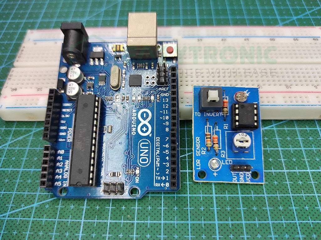
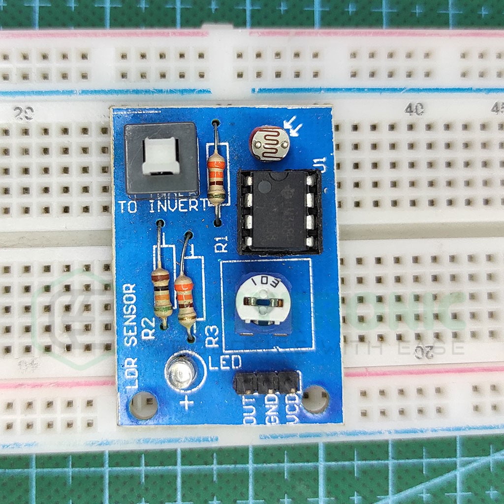
LDR Sensor Module
The term LDR is an acronym for Light Dependent Resistor. Yes, it is a type of resistor that gives resistance values, but we need voltage signals from it. To answer this question, we need to look into its structure and circuit. If you have made a laser circuit, then you might have used it and know how it works.
It is a resistor that is filled with one of these substances, namely Cadmium Sulphide (Cds), Cadmium Selenide (CdSe) or lead Sulphide (Pbs). This material is filled in a zigzag pattern on the ceramic insulating base. The ends of the base are attached to the metal terminal to make contact with the substance filled in a zigzag pattern. The whole structure is covered with transparent resin to provide insulation and allow the LDR to have exposure to light.
The working of LDR is quite simple if you have studied the photoelectric effect in higher classes. The exposure to light makes the electrons in the substance atoms jump to the conduction band from the valence band. This increases the resistivity of the substance. This allows the current to conduct from the substance, hence providing a path of resistance to the flow of current. We can also say that the intensity of light is inversely proportional to the resistance of the LDR.
The LDR sensor module is built around LM358P, which is a low-power Dual Op-Amp that amplifies the voltage signal coming from the LDR. The module also provides a potentiometer to adjust the output to the microcontroller. The input voltage is compatible with all the boards, but the module only gives digital output. For analog output, you need to have other versions than the one I have.
Arduino UNO
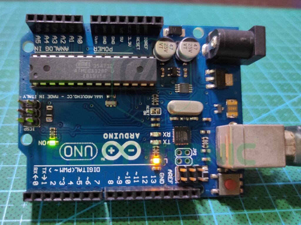
This is one of the inexpensive microcontroller boards that is highly recommended in the market. This board is easily accessible and reasonably priced in both offline and online markets. It provides a lot of helpful features at this pricing point, making it a comprehensive package for a beginner. Additionally, compared to most other boards, it offers greater durability.
The ATMEGA328PU microcontroller used in the Arduino UNO is packaged in a DIP-28 format. The DIP package houses the majority of the components on this board. As a result, it is easier to fix in the event that the circuit board malfunctions. An 8-bit CMOS microcontroller built on the AVR platform, the ATMEGA328PU can operate at a 16MHz clock rate. Additionally, you may program this IC using a separate FTDI programmer.
The Board has enough memory and storage to run all kinds of code. It has 32 KB of programmable flash memory and 2 KB of SRAM, which is more than enough for even some large projects. More importantly, because the board is inexpensive, this design is ideal for experiments. Additionally, it contains 1 KB of EEPROM, which can continue to store data even after new code uploads.
A suitable number of pins are included with the Arduino UNO. It can operate many devices thanks to its total of 23 I/O pins. There are 13 digital pins in total, 6 of which are PWM pins. Additionally, it offers 6 Analog pins with a 10-bit resolution, which is excellent for beginners. Moreover, it offers both 3.3V and 5V power supplies, along with another pin for additional purposes.
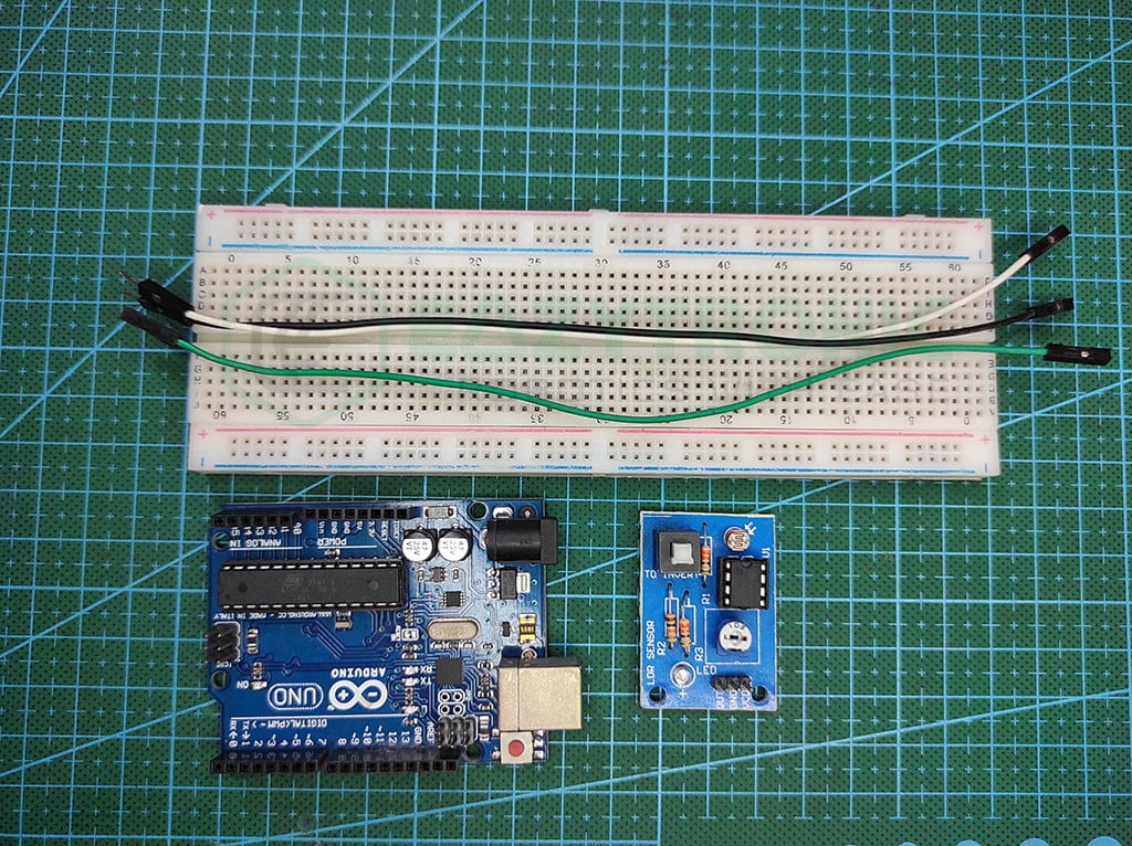
Material Required
- Arduino UNO
- LDR Sensor
- Breadboard
- Jumper Wires
- A light source to manipulate the resistance value
- A system to program Arduino
Fritzing Schematic
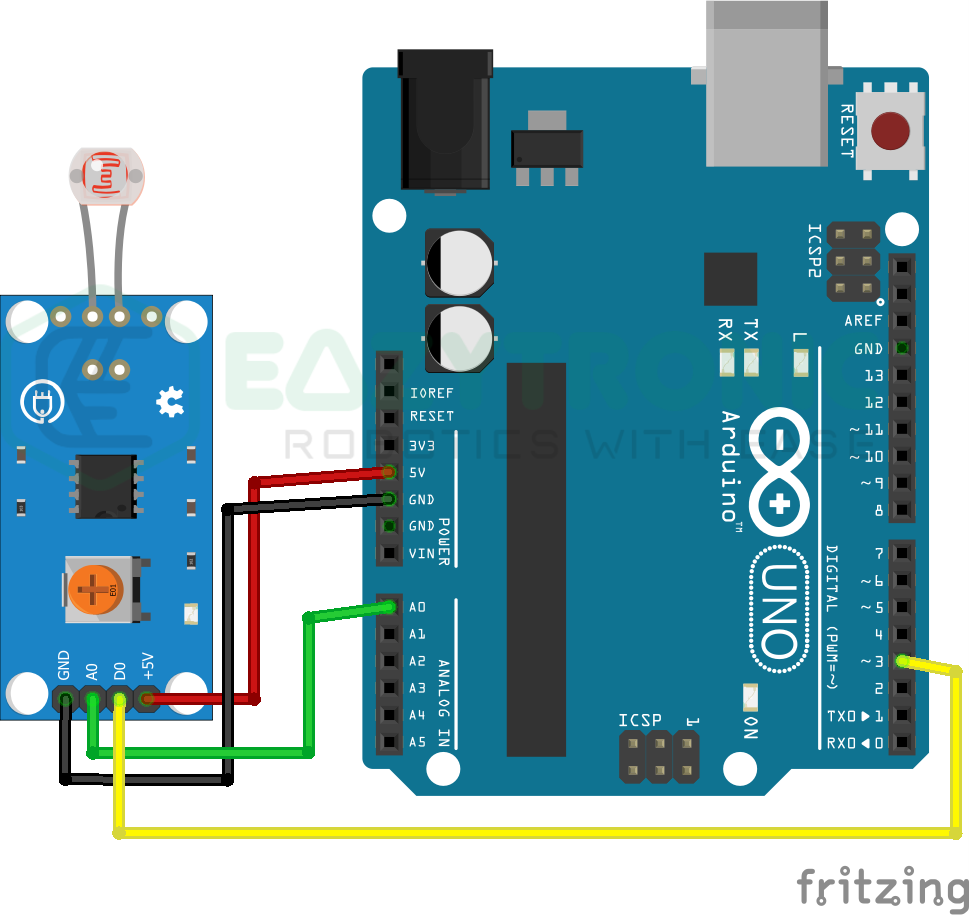
Wiring
| Arduino UNO | LDR Sensor |
|---|---|
| 5V | +/Vcc |
| GND | -/GND |
| D3 | DO |
| A0 | AO |
Programming Arduino UNO
Once you have completed all the above steps and connected all the components together as mentioned in the above schematic. You can now proceed towards starting to prepare your system to program the Arduino UNO. Beginners who are new to this field must download the Arduino IDE from the official download website. On the other hand, those who have already downloaded the IDE beforehand must need to update the libraries and board definitions to the latest version. If you need help, then read this detailed article for the steps from here.
Code
Below is the code for LDR with Arduino UNO. I have told you before that the version of the sensor I have only gives digital output, however for convenience I’ll give both codes and explain them separately. So make sure to read the explanation section for the required code.
#define ldrd 3
#define led 13

void setup(){
  pinMode(ldrd, INPUT);
  pinMode(led, OUTPUT);
}

void loop(){
  if(digitalRead(ldrd)==HIGH){
    digitalWrite(led,HIGH);
  }
  else {
  digitalWrite(led, LOW);
  }
}
#define ldra A0
void setup(){
Serial.begin(9600);
pinMode(ldra, INPUT);
}
void loop(){
Serial.println(analogRead(ldra));
}The above codes are given separately, however, they can be merged into one if you want. For this, read the mq3 with Arduino UNO article. Additionally, you need to save the code with some meaningful names so that you do not forget them. I have saved them with “ldr_arduino_d.ino”, “ldr_arduino_a.ino”. Remember, you cannot give spaces in the name, or else it will show an error.
Explanation
This is the most important section as you need to read the explanation of the code for editing the code as per your need. The explanation is divided into two sections, you can read the corresponding one.
Digital Code
#define ldrd 3
#define led 13
We start the code by defining the pins to which the sensor is connected. As we’re currently using the digital output, we only define the digital output pin along with an LED pin to show the status of the sensor. I have used it here define macro argument, you can use the int variable also to store pin information. Moreover, if you wish to change the pin for LED you can do that but make sure to change the schematic and connection also.
void setup()
void setup(){
  pinMode(ldrd, INPUT);
  pinMode(led, OUTPUT);
}
Next is the setup section, which includes the statement that needs to be executed once during the whole program cycle. As we make sure to simplify the code, only pin modes will be defined here for the pin for the sensor and LED. For the LDR sensor, the pin must be defined as the input pin as we’re receiving the data, while for the LED pin, it must be defined as the output pin.
void loop()
void loop(){
  if(digitalRead(ldrd)==HIGH){
    digitalWrite(led,HIGH);
  }
  else {
  digitalWrite(led, LOW);
  }
}
In the loop section, we’ll write the main code, hence it needs to be precise. So to make things starlight forward, I start the code with the condition to check the input from the sensor. In the if condition, I check for the input from the sensor, whether it’s HIGH or LOW. If it’s HIGH, then the LED will glow accordingly. Otherwise, the LED will remain off, you can also do some other tasks like using two LEDs to indicate on-and off situations.
Analog Code
#define ldra A0To begin with, we define the pin to which we attach the Arduino UNO’s A0 pin to the Analog Out pin of the LDR sensor. You can also adjust the pins to suit your preferences, however, I’ve gone with A0 for the most typical example. Additionally, you might put the pin in an int variable; but, the define macro argument offers advantages that a programmer might easily understand
void setup()
void setup(){
  Serial.begin(9600);
  pinMode(ldra, INPUT);
}
We will merely start the Serial communication and set the pin mode for the pin to which the LDR sensor is connected in the setup section because there isn’t much else to write. The serial transmission operates at a 9600 baud rate, but you can alter it as you choose. Additionally, you may show this on any display if you’d like to because these articles explain how to use other displays.
void loop()
void loop(){
  Serial.println(analogRead(ldra));
}
We only need to print the value that the sensor is giving us in the loop section. We have already started the serial communication for this. Now, all we need to do is type Serial.println(“value”); to print the value. I made a small adjustment to the code, substituting the analog Read function for the value. The value is returned by this function in integer format. Because of this, there is no need to store the value and provide the board with an extra variable to store.
With this we’re done with the LDR with Arduino UNO demonstration, if you need any help then write down below. I’ll make it clear ASAP.