
Welcome friends, I’m back with ST7789 with Arduino, another interesting article in the Arduino Series. In this article, we’ll be discussing how to connect ST7789, 240 × 240, 65k color display with Arduino UNO. Arduino UNO is one of the easiest development boards available in the market. While if we talk about the display then it is rather hard to say anything about it as there are many displays available in the market. However, this is the simplest color display you can find that is compatible with most development boards. So without wasting any more time, let’s start today’s session.
Arduino & ST7789 in Brief
ST7789 Display
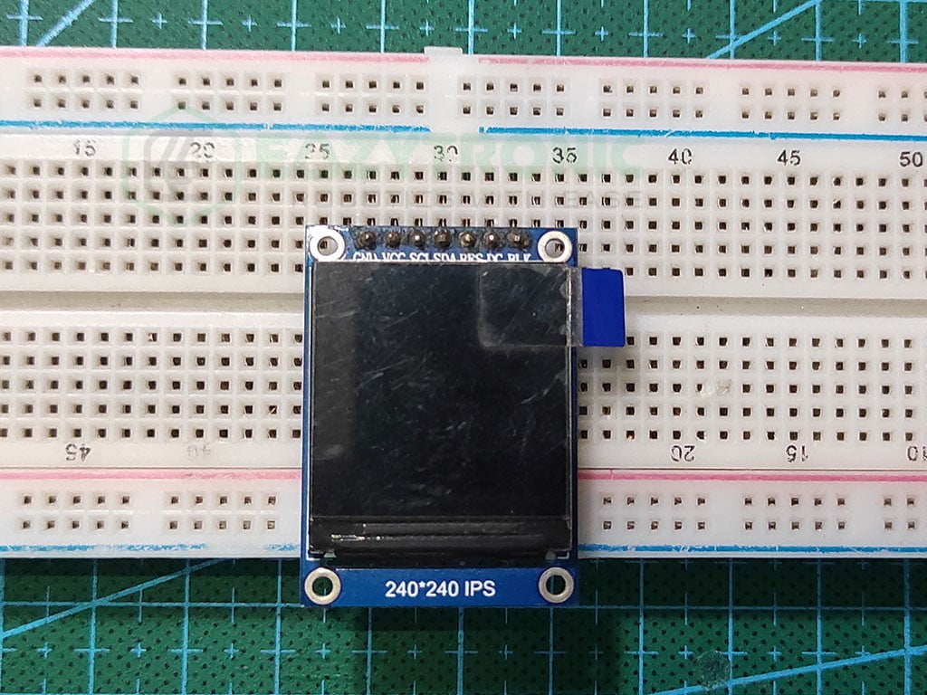
ST7789 is one of the most easily available color displays in the market. The one I’m demonstrating comes in a rectangular size. It is a 1.3” IPS LCD color display, which comes with a 240×240 resolution. The viewing angle of the display is ± 80°, which makes it subtly difficult to view from the sides. Moreover, it comes with 65k color accuracy and supports hardware scrolling that enables it to smooth scroll content without much effort of software processing. This makes it a perfect square-shaped small display for portable devices.
It communicates via SPI protocol, which makes it easier for most of the microcontrollers to use it. However, there is a drawback, it works strictly on a 3.3V logic level that needs to be taken care else you’ll fry your display. The driver used for driving the display is ST7789V, through which this display got its name. The display comes with an onboard 5v regulator that enables it to use it with the board not having a 3.3V supply. However, it is recommended to check for the version you have, as the one I have might differ from yours.
The support for this display is widely available on the internet such that, you can interface this display with Arduino, Raspberry Pi, ESP32, and many more microcontrollers. The display has 7 pins among which 2 are power pins, 4 data, and control pins and the last one is the backlight control pin.
Arduino UNO
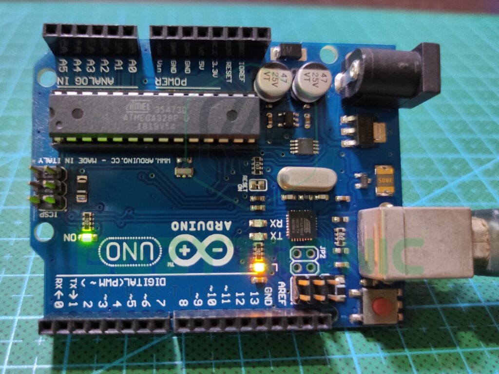
Arduino UNO is among the famous microcontroller that a beginner can use. Despite it being cheap, it consists of all the necessary communications protocols and functions that a normal microcontroller must have. Moreover, this board has more scope of repairability than any other microcontroller, this is because it is based on ATMEGA328PU which comes in the DIP-28 package. This enables the user to use multiple main IC and a single board to program and store different codes just with a swap of the IC. ATMEGA328PU is an AVR-based 8-bit CMOS microcontroller that operates on a frequency of 16 MHZ. Thus, this board might be a bit slow in terms of processing power as compared to ESP32 and Raspberry Pi boards.
It comes with 2 KB of SRAM paired with 32 KB of programmable flash memory, which is quite enough compared to a beginner’s POV. Not only this, but it also contains 1 KB of EEPROM that can store data even after the board is re-flashed until it is especially removed. If we talk about the pin provided, then it has 23 pins available for complete user operations. Among these there are 13 digital Pins and 6 analog pins that do their job perfectly. Moreover, there is s group of 6 PWM pins within the 13 digital pins and other communications for the board to perform.
The analog pins can work at 10-bit resolution, which is great for such a low price point microcontroller. In addition to this, it can also provide both types of power supply, 5V, and 3.3V. Overall it is a complete board available to beginners with a lot of functionality.
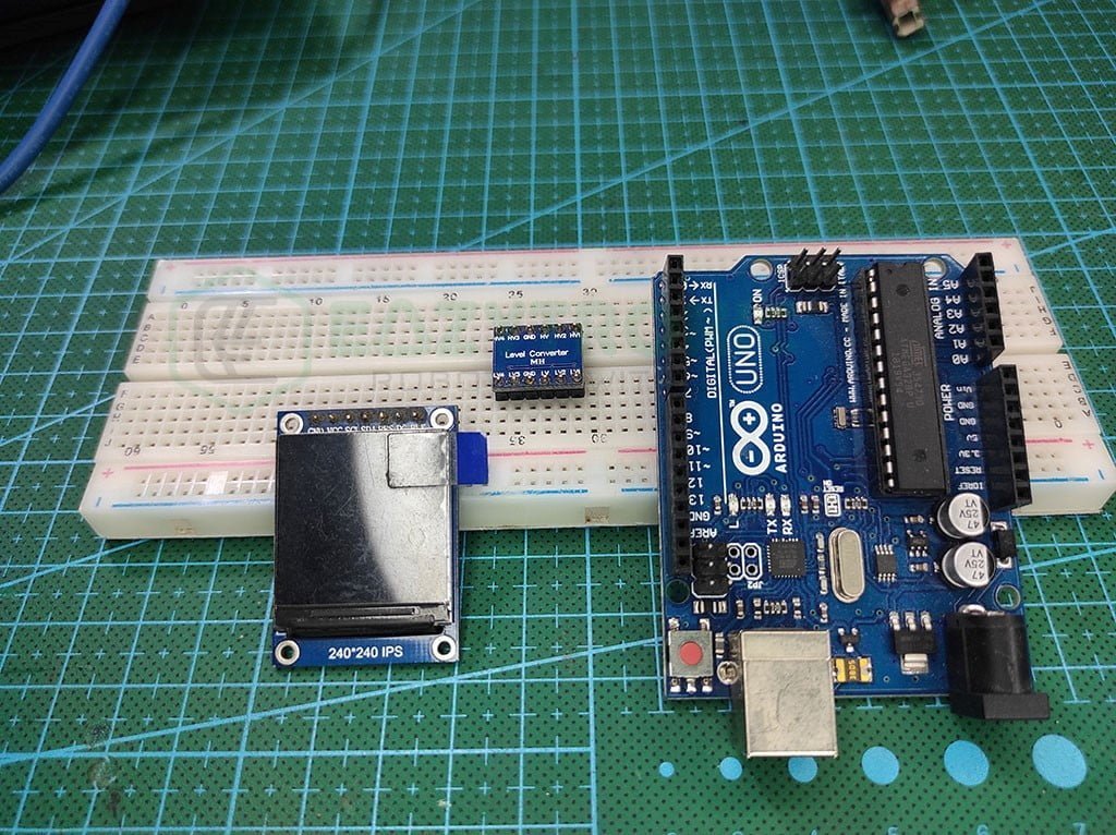
Material required
- Arduino UNO
- ST7789, 240×240 display
- A logic level converter
- Breadboard
- Jumper Wires
- A system to program Arduino Board
Fritzing Schematic
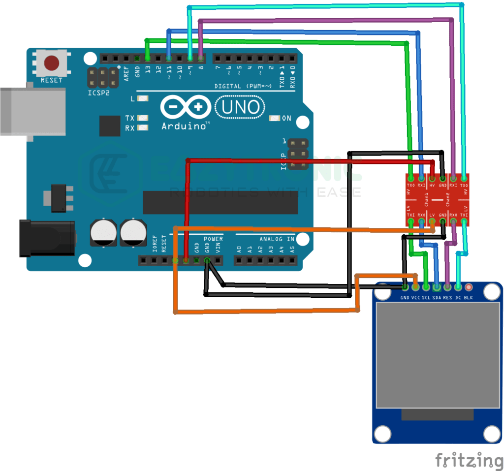
Wiring
| Arduino UNO | LOGIC LEVEL CONVERTER |
|---|---|
| 5V | HV |
| 3.3V | LV |
| GND | GND |
| D13 | HV1 |
| D11 | HV2 |
| D9 | HV3 |
| D8 | HV4 |
| ST7789 LCD | LOGIC LEVEL CONVERTER |
|---|---|
| Vcc | LV |
| GND | GND |
| SCL | HV1 |
| SDA | HV2 |
| RES | HV4 |
| DC | HV3 |
NOTE: The reason I have used the LOGIC LEVEL CONVERTER is that the display is of 3.3V logic level, while the Arduino is of 5V. So to make sure that the display didn’t get harmed, using a logic level converter is s good choice.
Programming Arduino UNO
This is one of the important sections of the article, as from here we’ll be giving code and explaining it from line to line. Before that like every other time make sure to update all the board and library definitions. Also, make sure that you are running the latest version of the Arduino IDE. In addition to this, If you are new to the Arduino Basic, then make sure to read the Arduino IDE introductory article for a subtle grasp of the topic and learn excitedly. With this, let’s begin.
Installing Library
Once all the above-directed things are checked, then you can install the library for the display to work. The version/model of display available to you is not known to me, therefore I’ll give code for all types of display. However, the code is only tested on the display available to me. So for any issues related to the display not working, right down below in the comment section. I’ll make sure to resolve it asap.
To install the library you can use the inbuilt library search and install section of the IDE. For this, just select the 3rd icon on the left menu. A library search menu will open, there write “st7789” and download the Adafruit version of the library. Wait for the installation, once done now you can use the library. For reference, below is an image attached.
Code
Below is the code for the display to work. The code provided is the simple one for just testing the display. For more operations and functions, you can visit the library’s GitHub page. However, in the upcoming projects, I’ll explain the working of more functions.
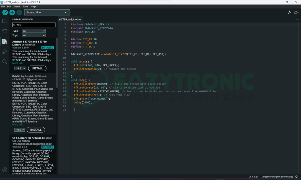
#include <Adafruit_GFX.h>
#include <Adafruit_ST7789.h>
#include <SPI.h>

#define TFT_CS 10
#define TFT_RST 8
#define TFT_DC 9

Adafruit_ST7789 tft = Adafruit_ST7789(TFT_CS, TFT_DC, TFT_RST);

void setup() {
  tft.init(240, 240, SPI_MODE2);
  tft.setRotation(2);
}

void loop() {
  tft.fillScreen(0x0000);
  tft.setCursor(10, 50);
  tft.setTextColor(ST77XX_GREEN);
  tft.setTextSize(3);
  tft.print("EAZYTRONIC");
  delay(2000);
  }
The above code uses the Adafruit Library, but you can also use other libraries available on the internet. However, I’m familiar with this library, hence I used it. Also further, I’ll explain the use of the Logic level converter I use in between connections. You can save the code with any name but saving them with something related is a good idea. Therefore, I advise you to save it with “st7789_arduino.ino”.
Explanation
This is the last and important section of the article, here I’ll explain the code line by line. If you carefully pay attention to the explanation, afterward you can edit the code according to your wish. So let’s start. There are only basic functions demonstrated here, so for more functions kindly refer to the GitHub page.
#include <Adafruit_GFX.h>
#include <Adafruit_ST7789.h>
#include <SPI.h>
First, we include some libraries that are needed for the code to compile and the display to work. If you are a beginner, then you might be asked to install several other libraries while installing the st7789 library. The Adafruit GFX library is a Universal library that is used by many other driver libraries for different displays. Precisely, the Adafruit GFX library is the main library that contains all the functions like drawing circles, writing text, and many others. Lastly, we include the SPI library to enable SPI communication. Make sure you connect the right pins, or else the code might not work.
#define TFT_CS 10
#define TFT_RST 8
#define TFT_DC 9

Adafruit_ST7789 tft = Adafruit_ST7789(TFT_CS, TFT_DC, TFT_RST);
Next, we define some pins for the display to work. The three pins that are included in all models of displays are RES, CS, & DC. D10 is the preferred or company-designated pin for the CS pin in SPI communication. The model I have doesn’t have the CS pin, therefore, I’ll use the RES and DC pins. Check-in your model what pins are included in your and use the pins. Next, we create a variable object for the LCD we have connected, this variable will now be used further for every function we perform. The syntax of the line is like Adafruit_ST7789 <varaible> = AdafruitST7789(CS, DC, RES=-1), by default, the RES pins are connected to the microcontroller RESET pin.
void setup()
void setup() {
  tft.init(240, 240, SPI_MODE2);
  tft.setRotation(2);
}
Further, we have a setup section that runs only once and therefore contains the line that needs to be executed once throughout the program. In the first line, we initialize the display with the correct resolution of the display. Along with this, you may or may not pass the SPI mode parameter. This parameter is useful for the display of different versions to make it work like the version I have to work on the SPI Mode 2. On the other hand, the displays that have the CS pin might work on SPI Mode 0. This you have to find out by yourself, or you can check about this on the internet. Next, I rotated the display by 180 degrees.
Here the 2 refers to the 3rd quadrant and the origin point is the top right of the display in the default style. In addition to this, you can rotate the display to any quadrant that corresponds to 0–3 numbers, respectively.
void loop()
void loop() {
  tft.fillScreen(0x0000);
  tft.setCursor(10, 50);
  tft.setTextColor(ST77XX_GREEN);
  tft.setTextSize(3);
  tft.print("EAZYTRONIC");
  delay(2000);
  }
The loop section of the code runs repeatedly and performs the task written within it. In the first line, we fill the display with Black color(0x0000 = BLACK, 0xffff = white). Many other color codes are pre-initialized that you can use. Next, we set the cursor to the desired position(x,y). Further, I change the color of the text to green to make it visible. Further, I change the font size of the text to 3. The size of the text depends on the don’t style you use, so make sure to experiment with this. Lastly, we print something on the display to check that the displays work. In the end, we put a delay of 2s to make the difference appear.

With this, we have completed the demonstration of the ST7789 with Arduino. If you face any issues, then make sure to comment down below, and I’ll try to solve them ASAP.