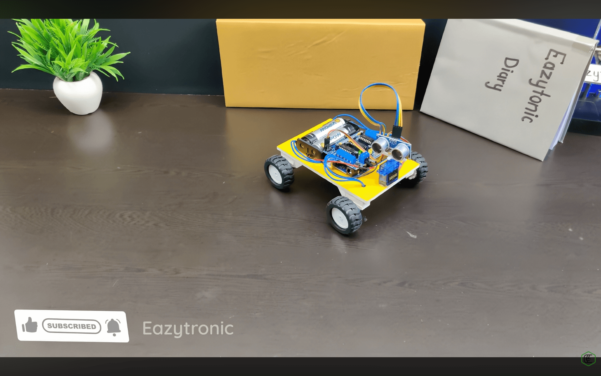
Obstacle avoidance sounds simple, but if we talk about non-living things now, this term becomes fascinating. Obstacle-avoiding car, this is one of the most demanding and rather simple projects to start with in this broad field of robotics. But the question arises, how to make an obstacle-avoiding car? For this, we need to learn about the working of the car, its components, and most importantly, how the code works.
Before we begin, I must advise you to check out our detailed post about the HC-SR04 Ultrasonic sensor. Also, to understand its working and a basic tutorial with Arduino UNO. Also, check out the basic tutorial of the ultrasonic sensor with Arduino UNO here. With all things done, let’s start with the project, finally!
Components Required for obstacle obstacle-avoiding car
Here’s what you’ll need to make your own obstacle-avoiding car:
- Arduino UNO
- HC-SR04 Ultrasonic Sensor
- SG90 Servo
- L293D Motor Driver Shield
- N30 Gear Motor (wires soldered) x4
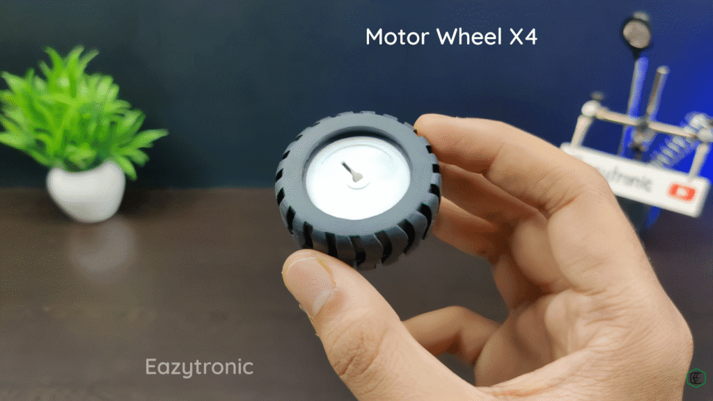
- Wheels x4
- Sun Board/ MDF Board (from a carpenter or stationery shop)

You can easily find all these components online or in local electronics shops. Below are brief introductions about each component:
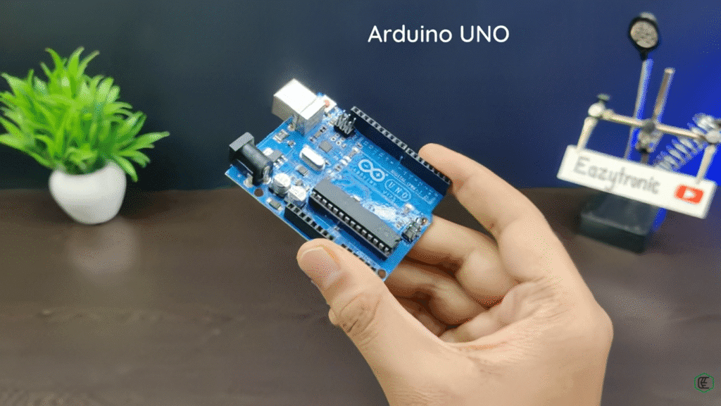
Arduino UNO
Arduino UNO is among the beginner-friendly boards, and in this project, we’ll be using this board to make it. This Board had 13 Digital pins and 6 Analog pins. It has 6 PWM pins for driving the motors. Moreover, it supports I2C, SPI, and UART communication protocols. It also includes a 10-bit ADC for reading values from the Analog Output sensors. For power outputs, we have 5V and 3.3V, with which we can power our electronics, but within Arduino power limits.
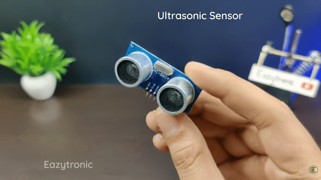
HC-SR04 Ultrasonic Sensor
One of the major components of the obstacle-avoiding car is the HC-SR04 Ultrasonic Sensor. For obstacle avoidance, the main thing is to detect them at a safe distance. The entry-level sensor for this is the Ultrasonic sensor HC-SR04. It works on the principle of reflection of sound. The two speaker-like transducers on the Ultrasonic sensor emit and receive ultrasonic sound waves of 40KHz. To estimate the distance, we measure the time between emission and reception of the ultrasonic sound. Further, with a simple formula, we find the distance
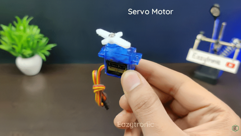
SG90 Servo
A servo motor is a type of actuator that converts the rotatory motion into the physical resistance to change in position. The SG90 servo features a small motor that, in combination with gears, increases the torque of the motor and enhances its weight-holding capacity. There are many other servo motors with more torque, but that depends on the application. However, for the current project, we only need to rotate the ultrasonic sensor, which doesn’t require much force.
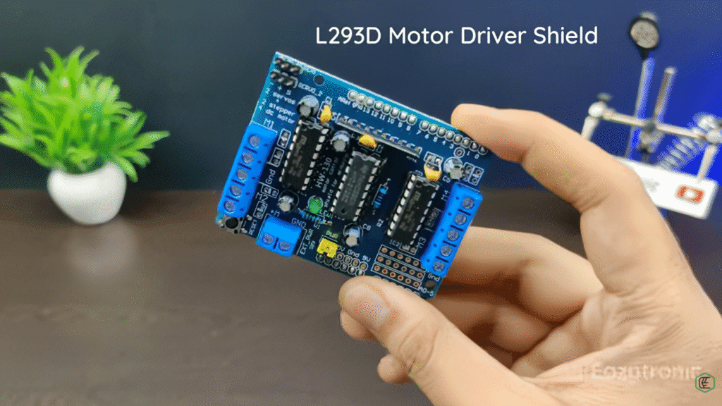
L293D Motor Driver Shield
L293D is the main driver IC with a dual H-Bridge for controlling two motors simultaneously. Combining both ICs can drive 4 motors simultaneously. In combination with this, it also consists of 74HC595, a shift register. This extends the Arduino’s 4 digital pins to 8 pins with speed and direction control. Along with this, the shield also has pins for analog and servos, along with power connectors.
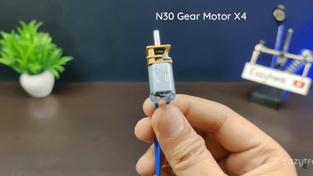
N30 Gear Motor
These are high rpm and decent torque gear motors suitable for small projects that have constrained space but require the high speed and torque capabilities. These motors come in many power ratings, but the ones we are using run on 5V. Please check the datasheet of the motors for the correct ratings.
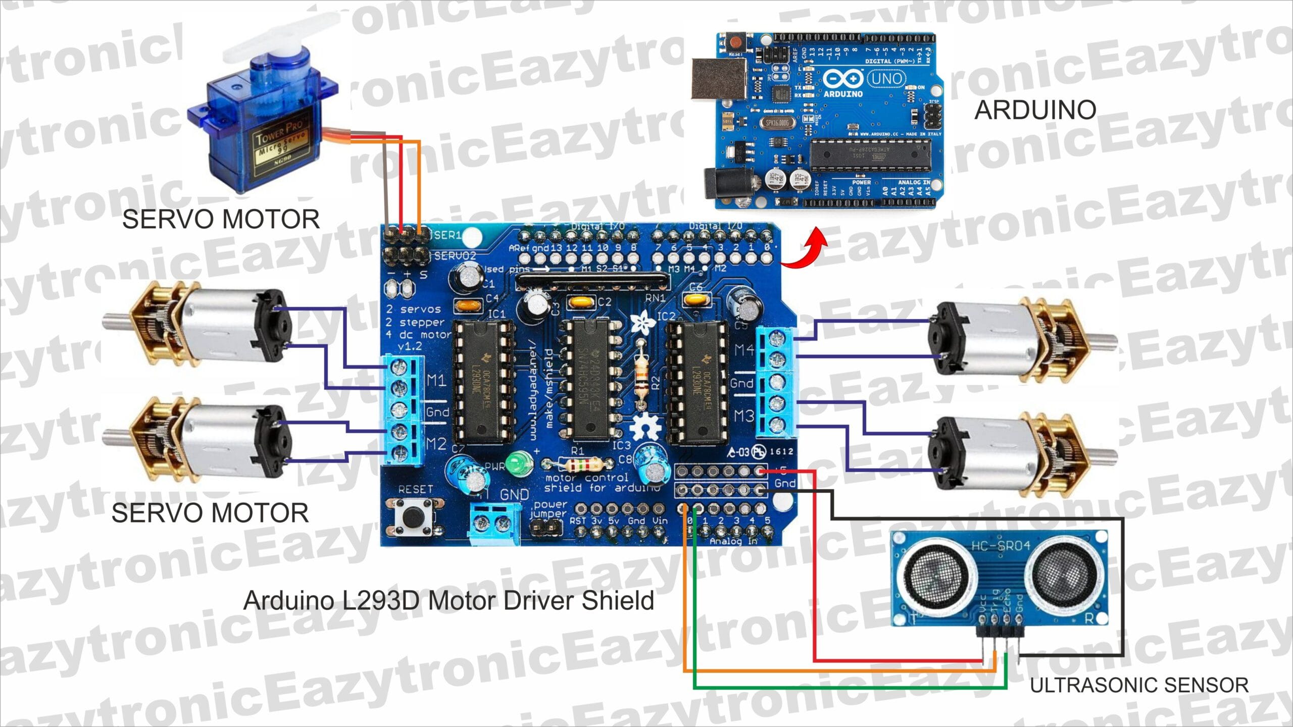
Circuit Diagram for obstacle obstacle-avoiding car
Now comes the main part of connecting components for the obstacle-avoiding car and preparing electronics. As we are using 4 motors, it is a 4WD(wheel drive) Car. Also, to keep things simple, we are using an HC-SR04 Ultrasonic sensor. But in the future, we’ll be using some advanced sensor to improve this. Below is the table for wiring the pins to each other.
| Motor Driver Shield | Component |
| A0 | Ultrasonic Trig Pin |
| A1 | Ultrasonic Echo Pin |
| M1 Screw Terminals | Motor 1 wires |
| M2 Screw Terminals | Motor 2 wires |
| M3 Screw Terminals | Motor 3 wires |
| M4 Screw Terminals | Motor 4 wires |
| Servo1 | Servo wires – → Grey wire + → Red Wire S ⇾ Orange Wire |
Working Principle of obstacle Obstacle-Avoiding Car
Now let’s learn about the working principle of the obstacle-avoiding robot. The robot has the necessary components/sensors that sense the nearby environment for any obstacles and move accordingly. The bot car, once on the ground, checks the forward distance via an ultrasonic sensor. Initially, we set a limit of 15 cm, which we can alter further as per our requirements
If the forward distance (checked continuously in a loop) is greater than the set distance, the bot continues to move forward until the distance is less than the set distance. Once the obstacle-avoiding bot comes within the in-front distance range of the set distance, it stops immediately. Further, it checks the left and right distance(not immediate right and left, but rather at some acute angle.
It compares the left and right distances and moves in the direction that has the greater distance ahead. To turn the bot car, we rotate the right and left side motors in opposite directions. This is to be set manually as the direction and speed must be first checked, then used in the actual code. Once turned in that direction, it again checks the forward distance, and the loop of code begins again
With this, the working of the bot car is completed, and you have made your own obstacle-avoiding bot car. The working of the obstacle avoidance car can differ for the different pieces of code. To completely understand the code logic, make sure to read the code explanation further to get an accurate idea, and also to alter the code as required.
Code & Explanation
Now comes the interesting part — the code! Now, let’s start with the code explanation for each section of the code so that you can modify the code as per your requirement.
#include "AFMotor.h"
#include <Servo.h>
First, we include the two libraries that are needed to compile the code, and hence make the code writing easier. Namely, these are AFMotor.h and Servo.h; these are libraries for the L293D Motor driver shield and for driving the servo motor. You can also manually control the Motor Driver shield, but that’ll be a tedious task.
#define echopin A1 // echo pin
#define trigpin A0 // Trigger pin

Servo myservo;

const int MOTOR_1 = 1;
const int MOTOR_2 = 2;
const int MOTOR_3 = 3;
const int MOTOR_4 = 4;
In this section, we define the pins for the Ultrasonic Sensor, create an object for the Servo motor, and pins for the motor driver shield. First, we start with defining the trig and echo control pins for the ultrasonic sensor, which are connected to A0 and A1 of the Analog header given on the Motor driver shield. Next comes creating an object for the servo motor with a variable named myservo, which will be further used to drive the servo.
In the next 4 lines, we define the pins for 4 Motors so each of them can be addressed individually and can be moved in a specific direction and with a specific speed for the task. If you are using some other library, you need to make sure to define your pins and other control pins if needed, in order for the shield to work. Moreover, if you are using only two motors, then you only need to use two motors, not 4.
AF_DCMotor motor1(MOTOR_1, MOTOR12_64KHZ); // create motor object, 64KHz pwm
AF_DCMotor motor2(MOTOR_2, MOTOR12_64KHZ); // create motor object, 64KHz pwm
AF_DCMotor motor3(MOTOR_3, MOTOR12_64KHZ); // create motor object, 64KHz pwm
AF_DCMotor motor4(MOTOR_4, MOTOR12_64KHZ); // create motor object, 64KHz pwm
Next, we create motor objects for driving the motors with a 64KHz PWM signal. It is important to define the PWM for the motor so that all of them rotate at the maximum speed when max PWM is given. Variables for the motors are your choice and can be changed as per user discretion.
int distance_L, distance_F, distance_R;
long distance;

int set = 20;
Here we create variables for the ultrasonic sensor that will store the forward distance, left and right distance. Along with this, we also create a long variable for storing the accurate distance values. Also, we create a limit on the distance at which the forward path is said to be cleared. If the distance fetched from the ultrasonic sensor is less than this limit, then the condition to rotate the car comes into action.
void setup() {
  Serial.begin(9600);           // Initialize serial port
  Serial.println("Start");

  myservo.attach(10);
  myservo.write(90);

  pinMode (trigpin, OUTPUT);
  pinMode (echopin, INPUT );

  motor1.setSpeed(180);          // set the motor speed to 0-255
  motor2.setSpeed(180);
  motor3.setSpeed(180);
  motor4.setSpeed(180);
}
Now comes the main part of the code, the setup section. We start by starting the serial communication at a 9600 baud rate to print the statement to the Serial Monitor, like the Start in the next line. Further, we attach the servo to pin 10 of the Arduino UNO. In fact, you don’t need to actually connect the servo to Arduino UNO you can just connect at the Servo Pin 1 header provided on the motor driver shield.
In the next line, we position the servo at 90 degrees as the write function of the servo library takes the angle as an argument. Thus allowing us to fix the position of the ultrasonic sensor straight facing the front part. In the next lines, we define the pin modes of the trig and echo pins of the ultrasonic sensor, which will be used to check the distance. The distance fetched is stored in either the forward, left, or right direction and is compared to the set limit as per the flow and condition of the code.
void loop() {
 distance_F = data();
 Serial.print("S=");
 Serial.println(distance_F);
  if (distance_F > set){
   Serial.println("Forward");
  motor1.run(FORWARD);         // turn it on going forward
  motor2.run(FORWARD);
  motor3.run(FORWARD);
  motor4.run(FORWARD);
    }
    else{hc_sr4();}
}
Now comes the loop section, which iterates the code and hence brings the car to life. Code starts with first checking the forward distance with the help of the Ultrasonic sensor and returns the value to the distance_F variable, also printing the distance to the Serial Monitor. If compares the distance with the set limit, and if the distance is more the the lines with which the car moves forward come into action.
However, if the distance is less than, we call a custom function named hc_sr4() which does the job of tuning the car. For more info about these functions, read the article further for complete information and understanding of the logic.
long data(){
  digitalWrite(trigpin, LOW);
  delayMicroseconds(2);
  digitalWrite(trigpin, HIGH);
  delayMicroseconds(10);
  distance = pulseIn (echopin, HIGH);
  return distance / 29 / 2;
}
Here, we make a custom function to calculate the distance from the ultrasonic sensor. The function turns the trigpin LOW/OFF for 2 microseconds to clear up any ongoing garbage signal and mark the path clear for transmission. After that, we turn the trig pin high for 10 microseconds to send the beam of Ultrasonic sound waves. and then again turning the trig pin LOW.
Just after that, we check the time pulse from the transmission of the ultrasonic waves and the reception of the waves at the start points. The time interval between gives the 2x time required for the sound waves to return after reflection from the obstacle/object. The function finally returns the distance in CM after calculating and converting it.
void compareDistance(){
  if (distance_L > distance_R){
  motor1.run(BACKWARD);   // turn it on going left
  motor2.run(BACKWARD);
  motor3.run(FORWARD);
  motor4.run(FORWARD);
    delay(500);
  }
  else if (distance_R > distance_L){
  motor1.run(FORWARD);  // the other right
  motor2.run(FORWARD);
  motor3.run(BACKWARD);
  motor4.run(BACKWARD);
    delay(350);
  }
  else{
  motor1.run(BACKWARD);  // the other way
  motor2.run(BACKWARD);
  motor3.run(BACKWARD);
  motor4.run(BACKWARD);
   delay(300);
  motor1.run(BACKWARD);   // turn it on going left
  motor2.run(BACKWARD);
  motor3.run(FORWARD);
  motor4.run(FORWARD);
    delay(500);
  }
}
compareDistance is another custom function that does the following task: it compares the distance on the left and right side of the car, and based on the condition, it turns to either right or left. Let’s understand the logic. First, we check the left and right distances with the help of the ultrasonic sensor and servo motor, in the variables distance_L and distance_R.
If the distance_L is greater than the distance_R, it turns left by rotating two motors backward and two forward. This way, our obstacle-avoiding car can turn left almost at a point. We surely have to give some delay for the motor to rotate and hence turn left, while in the else if condition, we make the bot rotate right by rotating two motors forward and two backward.
Lastly, in the else condition, we make the bot do the default movement, which is moving a little back and then rotating. With some delay for the lines to do their job, we finally make the car turn either right or left to whichever side there’s enough space for the car bot to move.
Below is the complete code for the car. You can copy and paste it and see your project coming to life.
#include "AFMotor.h"
#include <Servo.h>

#define echopin A1 // echo pin
#define trigpin A0 // Trigger pin

Servo myservo;

const int MOTOR_1 = 1;
const int MOTOR_2 = 2;
const int MOTOR_3 = 3;
const int MOTOR_4 = 4;

AF_DCMotor motor1(MOTOR_1, MOTOR12_64KHZ); // create motor object, 64KHz pwm
AF_DCMotor motor2(MOTOR_2, MOTOR12_64KHZ); // create motor object, 64KHz pwm
AF_DCMotor motor3(MOTOR_3, MOTOR12_64KHZ); // create motor object, 64KHz pwm
AF_DCMotor motor4(MOTOR_4, MOTOR12_64KHZ); // create motor object, 64KHz pwm
//===============================================================================
//  Initialization
//===============================================================================

int distance_L, distance_F, distance_R;
long distance;

int set = 20;

void setup() {
  Serial.begin(9600);           // Initialize serial port
  Serial.println("Start");

  myservo.attach(10);
  myservo.write(90);

  pinMode (trigpin, OUTPUT);
  pinMode (echopin, INPUT );

  motor1.setSpeed(180);          // set the motor speed to 0-255
  motor2.setSpeed(180);
  motor3.setSpeed(180);
  motor4.setSpeed(180);
}
//===============================================================================
//  Main
//===============================================================================
void loop() {
 distance_F = data();
 Serial.print("S=");
 Serial.println(distance_F);
  if (distance_F > set){
   Serial.println("Forward");
  motor1.run(FORWARD);         // turn it on going forward
  motor2.run(FORWARD);
  motor3.run(FORWARD);
  motor4.run(FORWARD);
    }
    else{hc_sr4();}
}


long data(){
  digitalWrite(trigpin, LOW);
  delayMicroseconds(2);
  digitalWrite(trigpin, HIGH);
  delayMicroseconds(10);
  distance = pulseIn (echopin, HIGH);
  return distance / 29 / 2;
}


void compareDistance(){
  if (distance_L > distance_R){
  motor1.run(BACKWARD);   // turn it on going left
  motor2.run(BACKWARD);
  motor3.run(FORWARD);
  motor4.run(FORWARD);
    delay(500);
  }
  else if (distance_R > distance_L){
  motor1.run(FORWARD);  // the other right
  motor2.run(FORWARD);
  motor3.run(BACKWARD);
  motor4.run(BACKWARD);
    delay(350);
  }
  else{
  motor1.run(BACKWARD);  // the other way
  motor2.run(BACKWARD);
  motor3.run(BACKWARD);
  motor4.run(BACKWARD);
   delay(300);
  motor1.run(BACKWARD);   // turn it on going left
  motor2.run(BACKWARD);
  motor3.run(FORWARD);
  motor4.run(FORWARD);
    delay(500);
  }
}

void hc_sr4(){
    Serial.println("Stop");
    motor1.run(RELEASE);         // stopped
    motor2.run(RELEASE);
    motor3.run(RELEASE);
    motor4.run(RELEASE);

    myservo.write(0);
    delay(300);
    distance_R = data();
    delay(100);
    myservo.write(170);
    delay(500);
    distance_L = data();
    delay(100);
    myservo.write(90);
    delay(300);
    compareDistance();
}
Video Tutorial
Below is the Video tutorial for the complete project. You can visit that for a more detailed building guide.