
Hey guys, I’m back with PIR Sensor with Arduino UNO demonstration. PIR sensor is one of the must-have sensors for every person as it can be used in many projects. PIR sensor is a basic sensor that is available very easily in the market and at a low cost. Additionally, there are many advanced versions of this sensor available that are somewhat not as easy to operate as this. Although this sensor offers fewer features, it is recommended for most of the projects that you’ll come through in the future. I have explained about this sensor in detail in the PIR Sensor article, make sure to read it for complete understanding. Now let’s dig deeper into the demonstration.
PIR Sensor and Arduino UNO in Brief
PIR Sensor
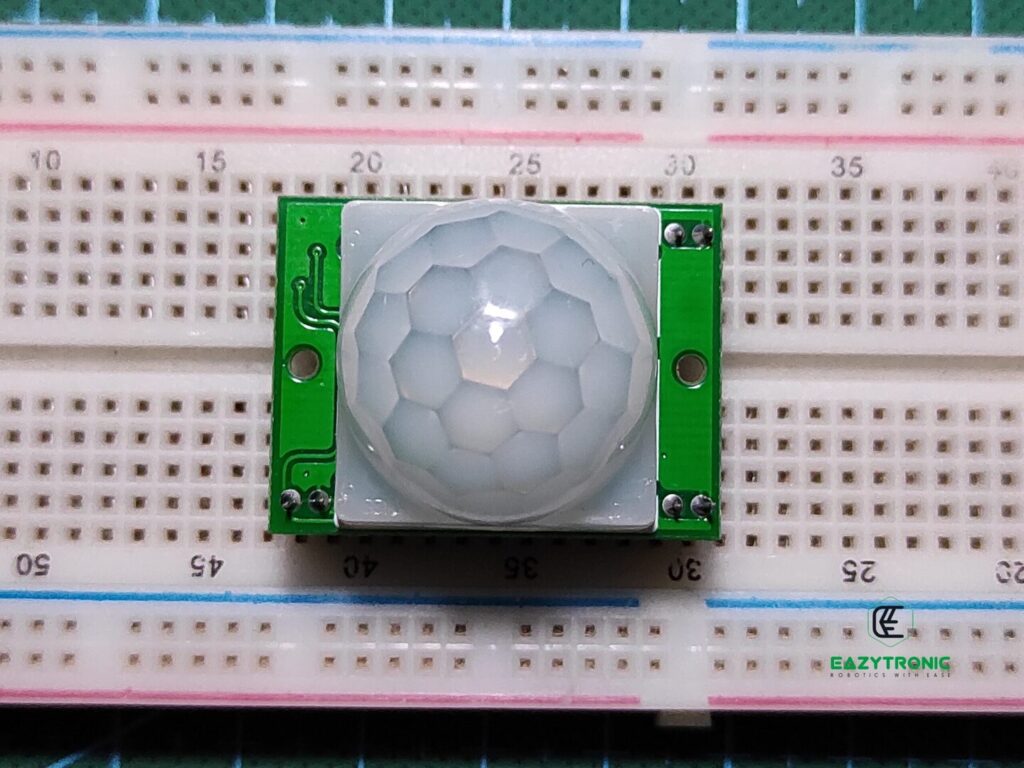
Passive Infrared is the complete name of the PIR Sensor. Passive infrared means it is different from the IR or Flame sensor that uses Infrared pairs of LED. Rather, it uses a different component that works on the same principle. The passive infrared sensor uses a type of Photodiode to detect Infrared light from a nearby environment.
Every being or object emits certain heat radiation based on its body temperature. These radiations travel in the form of IR waves, that get detected by this sensor. There is a more advanced version of this sensor known as the Microwave PIR Sensor. The metal sensor inside the Fresnel lens enclosure detected these waves and upon estimation of their path, it tells the movement.
The outer white covering of the sensor is a Fresnel lens that just directs all the waves onto the screen of the Photodiode. On the other hand, the sensor is not meant for use in direct light sources like fire and direct sunlight. As these conditions might make the sensor mistake heat radiation as the movement of the object and give you error values.
The sensor is compatible with all types of microcontrollers of both 3.3V and 5V logic levels. Also, the output is digital, so there is no need for more pins. However, you still need to adjust the time delay and sensitivity of the sensor. This can be done via the provided on-board potentiometer for precision.
Arduino UNO
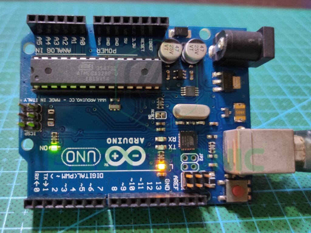
Arduino UNO is one of the most popular microcontrollers in the market. This microcontroller is very easily available and offers sufficient features for a beginner to start with. If we compare it to other boards at a slightly higher price point, then it seems to be a bit costlier. However, if we look at the durability of the board and replacing components in case of any malfunction, it stands at its price point.
Arduino UNO is built out of an ATMEGA328PU microcontroller, which is excellent for experiments. ATMEGA328PU is an AVR-based 8-bit CMOS microcontroller that comes in different packages, but here it is present in the DIP-28 version. The IC can operate at a frequency of 16MHz, which is optimal for most of the projects.
Next comes the specs it packs within itself. It has 2 KB of SRAM that can run tons of programs without any issues, but the user must know how to use the space efficiently. Moreover, it is paired with 32 KB of programmable flash memory that can store an ample amount of code to make a robot that we’ll be discussing in future articles. Additionally, it also has 1 KB of EEPROM, which is unique for such a small microcontroller.
Lastly, we take a look at the pins and power section. Arduino UNO has a total of 23 I/O pins that are totally controllable via the software/code. This includes 13 digital pins, among which there are 6 digital pins. Along with this, it has 6 Analog pins to play with analog values. The board can use all types of communication like SPI, I2C, Serial, and many more. Also, it has both types of power available, i.e., 3.3V and 5V. This makes it a complete package for beginners.
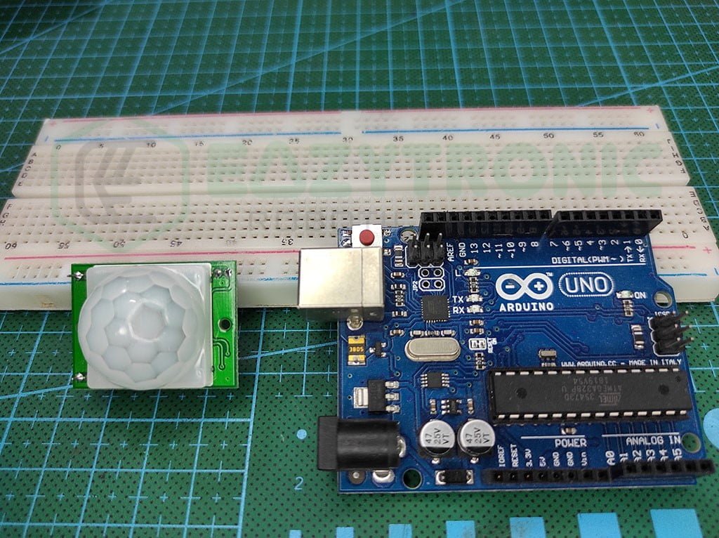
Material Required
- Arduino UNO
- PIR Sensor
- Breadboard
- Jumper Wires
- A system to program Arduino
- Screwdriver to trim the potentiometer
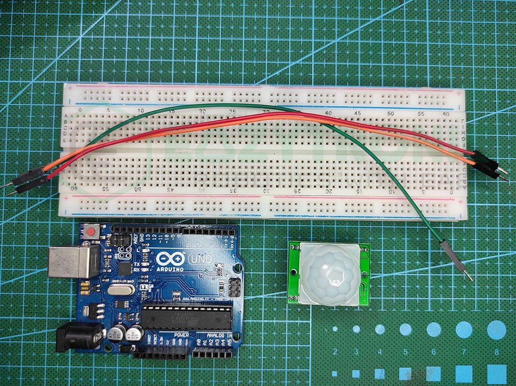
Fritzing Schematic
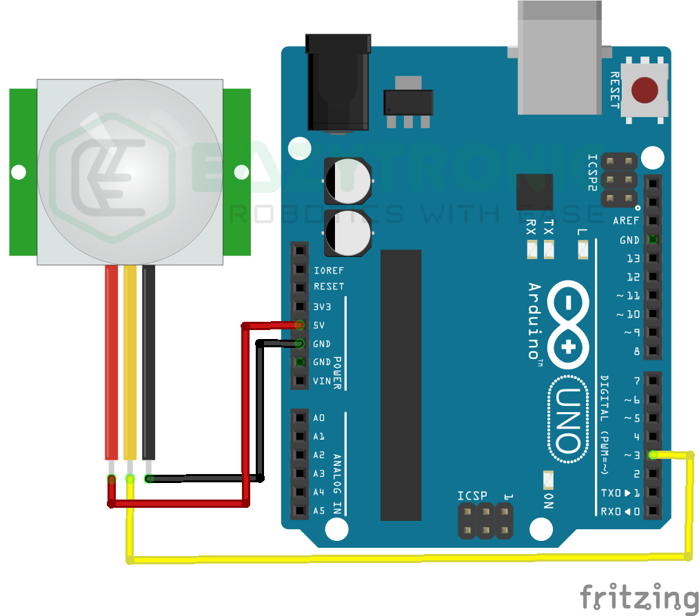
Wiring
| Arduino UNO | PIR Sensor |
|---|---|
| 5V | Vcc |
| GND | GND |
| D3 | OUT |
Programming Arduino
After you have connected PIR Sensor with Arduino UNO, you can now start the software to program the board. For this, first, make sure you have downloaded the Arduino IDE. Or if you have already downloaded it, then make sure to update it to the latest version. Along with this, also update all the board definitions and libraries to the latest version to avoid any error during compilation. If you are new to Arduino IDE and don’t know much about I then you can read about it in Arduino IDE Introductory article. In this, I have explained all the basic things about IDE along with Boards specifications and an example sketch of BLINK LED.
Code
This is the important section as code and explanation of the working of code is started from here. Therefore, it is advised to read this section carefully. Also, the code is tested on the Arduino UNO board with PIR Sensor new version, in which there are smd pads for mode selection.
#define pir 3
#define led 13

void setup(){
  Serial.begin(9600);
  pinMode(pir, INPUT);
  pinMode(led, OUTPUT);

}

void loop(){
  if(digitalRead(pir)==HIGH){
    digitalWrite(led, HIGH);
    Serial.println("MOTION DETECTED");
    Serial.println();
  }
  else {
  digitalWrite(led, LOW);
  }
  delay(100);
}
Save the above code with a reasonable name so that you can remember it. I advise you to save this with pir_sensor_with_arduino.ino, make sure to not use space in the name, or it will show an error while saving also whenever starting the Arduino IDE. Next, we’ll begin the explanation.
Explanation
Now we have reached the explanation part, one of the essential sections to focus on. Here I’ll be explaining the code line by line so that you can write your custom code. Also, several other instructions will be given on the working of code and sensor.
#define pir 3
#define led 13
In the first two lines, we create two macro variables that store the pins of the Sensor and LED. Here, I have used the on-board LED of the Arduino UNO, you can use any other and connect a separate LED on that pin. For the sensor pins as the output is digital, so you must use a digital pin of your choice. To keep it simple, I’ll be using the D3 pin.
void setup()
void setup(){
  Serial.begin(9600);
  pinMode(pir, INPUT);
  pinMode(led, OUTPUT);
}
In the setup section, we write code that needs to be executed once, but as we have nothing much to write, we’ll be initializing communication and defining pin modes. In the first line, we start a serial communication between Arduino UNO and System at the 9600 baudrate. You can change the baudrate at your ease, but make sure to change it in the Serial monitor also.
Further, we define the pin modes of the pins that we have defined above. For the PIR Sensor, the mode is INPUT irrespective of which mode the sensor is in. And for the LED, it is obviously OUTPUT. The PIR Sensor can be in two modes H (the one I’m demonstrating), in this mode the sensor detects the movement and gives the output. Meanwhile, the output timer will be reset every time it will detect movement, irrespective the previous timer is still going on or is finished.
The L mode differs slightly, it blocks the output during and current timer and adds the second detection to the queue as soon as the current going on timer ends. However, the sensor output logic level is 3.3V, so there is no need for a logic level converter for any microcontroller.
void loop()
void loop(){
  if(digitalRead(pir)==HIGH){
    digitalWrite(led, HIGH);
    Serial.println("MOTION DETECTED");
    Serial.println();
  }
  else {
  digitalWrite(led, LOW);
  }
  delay(100);
}
This is the last section of the code, the loop section. Here we write the code that needs to be iterated continuously. We begin the code with a condition, as I want to keep the code simple without any complications. The conditions read the input of the pin, on which the sensor is connected on. In the same line, it is compared whether the signal is HIGH or LOW. The syntax of such a line is digitalRead(<pin variable or number>) == HIGH.
If the output is HIGH i.e., motion is detected, then the LED on the Arduino UNO will blink continuously for 6-7 sec according to the least timer value. You can increase this by trimming the potentiometer. However, if the output is LOW then the LED will remain off and nothing will be printed on the Serial Monitor.
With this, we come to an end of the PIR Sensor with Arduino UNO. If you find any issues while programming the code, do let me know in the comment section.