
Hey friends, I’m back with RFID with Arduino UNO, another interesting article in Arduino Series. RFID is one of the most secure technology that is used in security projects. Not only it’s safe but can also be used very easily as needs very less resources. RC522 is a very common RFID module that can be easily found in offline and online markets. Although there are limitations to this module, it works very well overall. Moreover, the module is compatible with the 5V logic level also, which makes it useable with almost all microcontrollers. With this, let’s begin today’s discussion.
RC522 and Arduino in brief
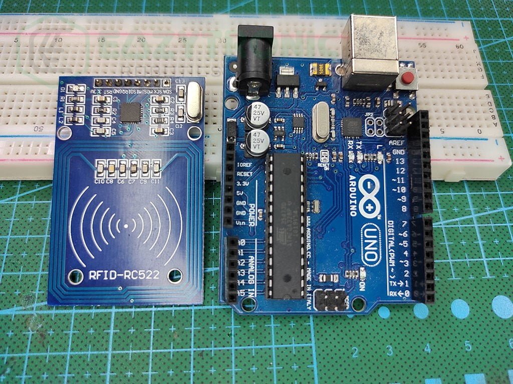
RC522
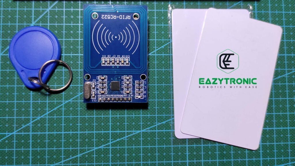
It is one of the most commonly used RFID modules with Arduino and other microcontrollers. RFID stands for Radio Frequency Identification and works on the most common cards available in the market. This module only has limited capabilities and is not something like hackers shown in movies. It is built out of the MFRC522 IC that can read only specific types of tags.
This module is 5V tolerant, so there is no issue like logic level conversion issue like in the previous articles. Moreover, the library is available on multiple platforms so you can use it with Raspberry Pi, ESP32, or Python and C++. This module supports ISO/IEC 14443 A/MIFARE type of tags.
It can also support other cards like access cards and so. However, the reading and writing data from and to tag are not guaranteed to be accurate as those are not supported. The module can be easily cloned for custom uses. But the issue is with the coil that is included in the PCB. The rest of the components are also SMD, which can be an issue while repairing. But the values of components are easily available in the through-hole type also.
The Antenna or coil used for reading and writing data is made into the PCB, this causes the problem for the custom schematics. More information about RFID RC522 is available in its detailed article.
Arduino UNO
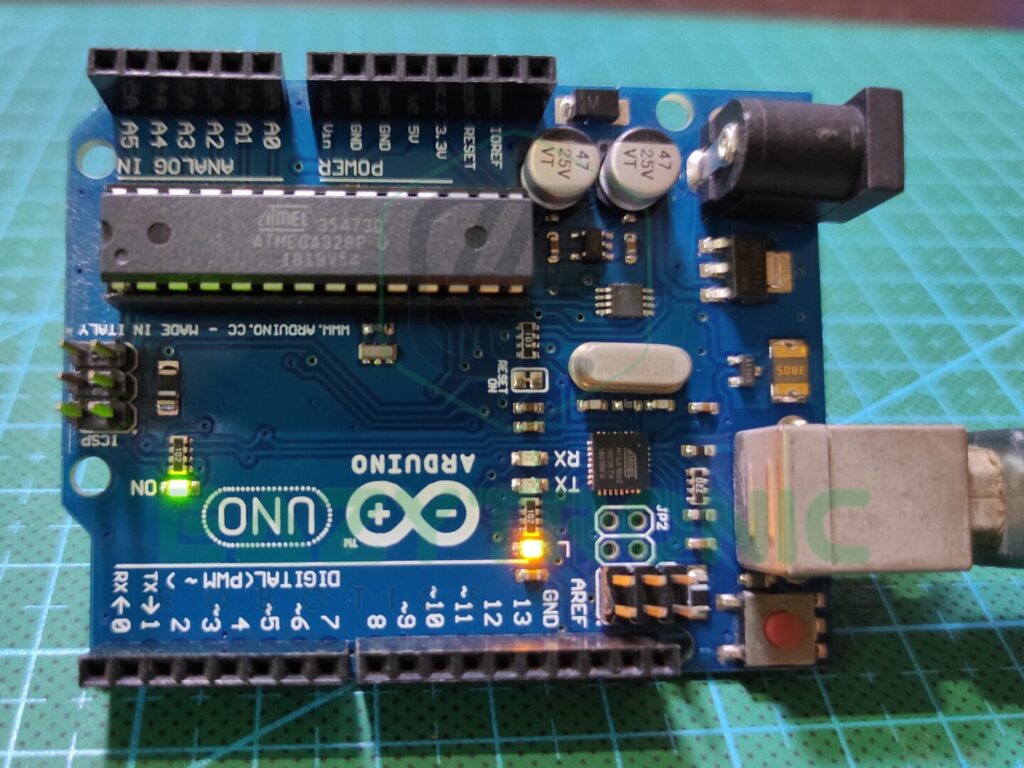
Arduino UNO is a very famous microcontroller among beginners and is quite easily available in the market. Not only, this board comes in low prices, but it is packed with some serious good stuff. The main thing that makes this board more famous because of its durability and repairability factors.
UNO Board is built out of an ATMEGA328PU microcontroller, which comes in many packages, but the one on this board is in DIP-28. ATMEGA328PU is an AVR-based 8-Bit CMOS Microcontroller that can operate at a frequency of 16 MHz. Thus, you can change the IC for storing multiples program on different chips. Moreover, you can also replace it if there is some issue with the board.
This board packs within itself 2 KB of SRAM, which is sufficient for most of the programs to run. Along with this, it is paired with 32 KB of programmable flash memory. It also has an EEPROM memory of 1 KB which sounds pretty less but at this price point having EEPROM is also a good thing. You can also attach an external SPI flash for more storage.
Lastly comes the pins and power supply available. Arduino UNO comes with a total of 23 I/O pins that include all the pins required for different communication. There are 13 Digital pins that include 6 PWM pins. Among those pins, two of them can operate at a higher frequency than the others. It also contains 6 Analog pins having 10-bit resolution.
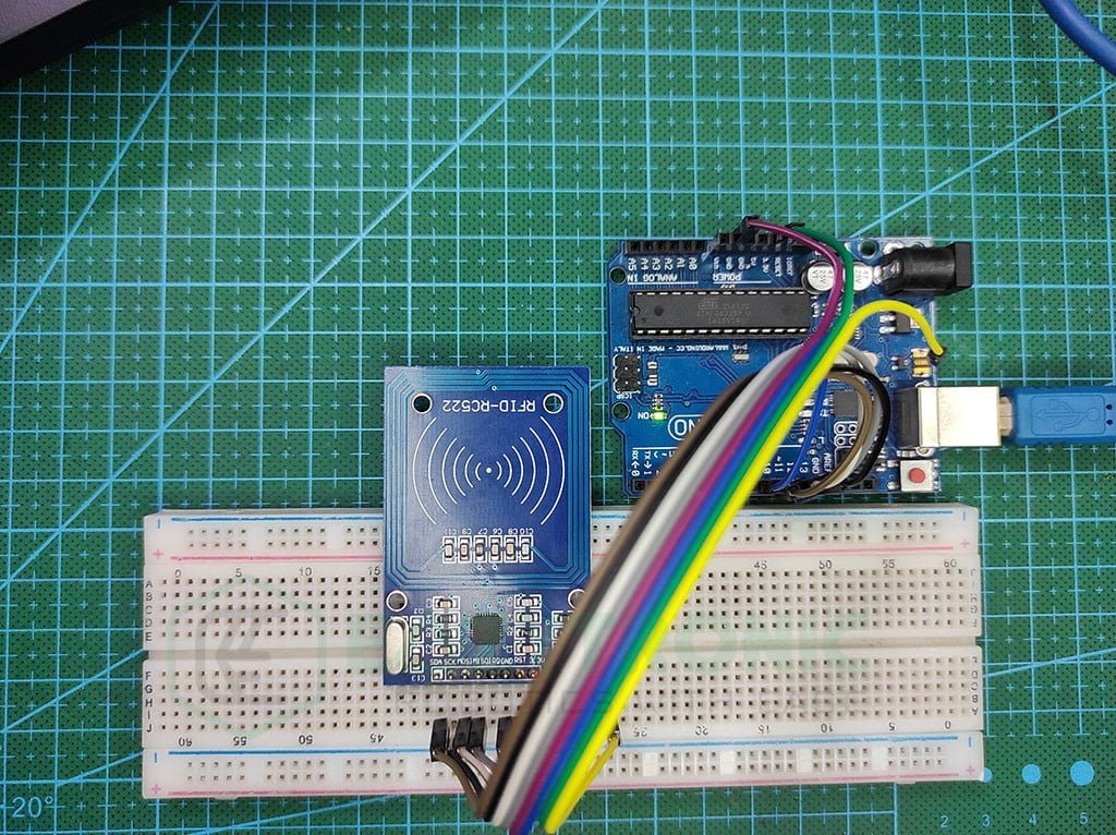
Material Required
- Arduino UNO
- RC522 RFID Module
- Breadboard
- Jumper Wires
- A system to program Arduino UNO
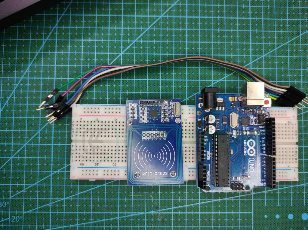
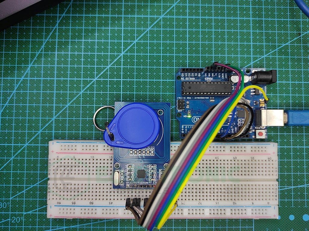
Fritzing Schematic
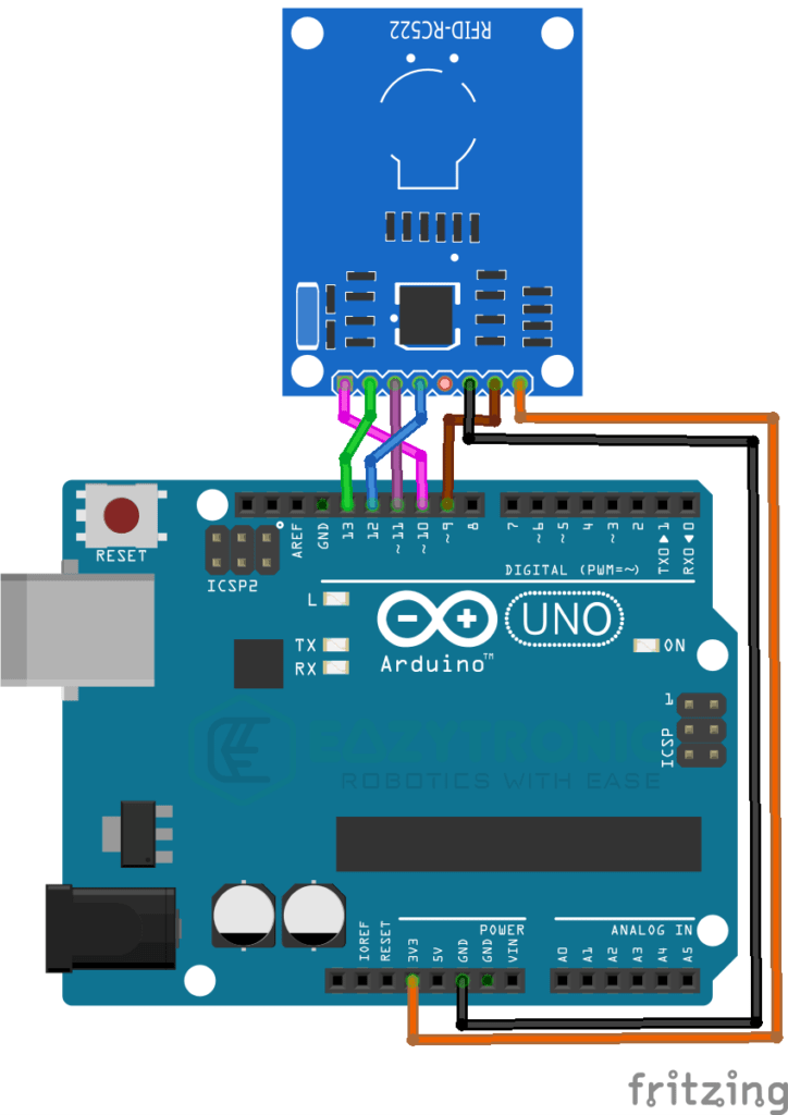
Wiring
| Arduino UNO | RC522 |
|---|---|
| 3.3V | 3.3V |
| GND | GND |
| D13/SCK | SCK |
| D12/MISO | MISO |
| D11/MOSI | MOSI |
| D10/CS | SDA |
| D9 | RST |
Programming Arduino
Once you have completed all the mentioned steps now you can start preparing your system to program code onto the Arduino UNO Board. For final checks, make sure you have downloaded the Arduino IDE and updated all the board definitions and libraries. If you are new to Arduino IDE, then read my introductory article on it. I have explained all the aspects of Arduino IDE along with an example sketch of Blink LED. Further, we’ll be learning how to install the library in Arduino IDE. Let’s continue.
Installing Library
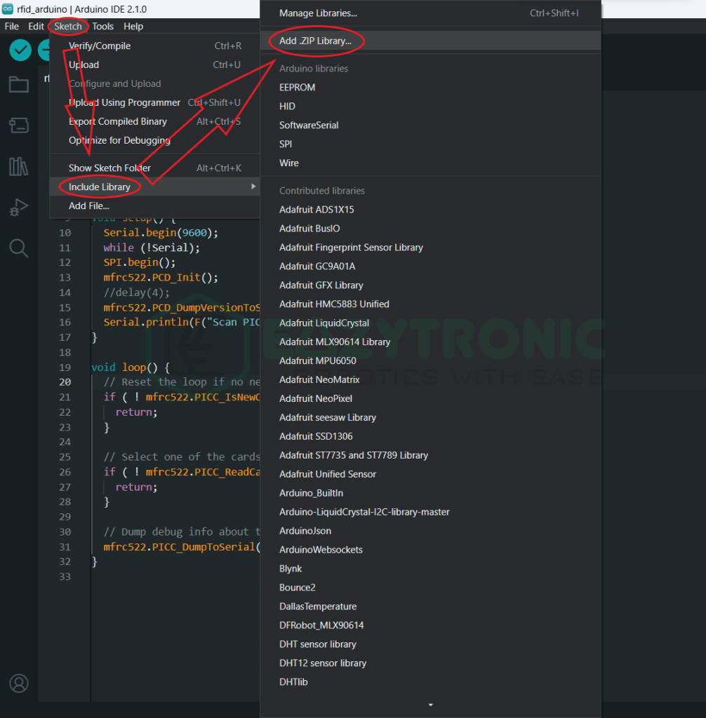
To install the library, make sure you have an internet connection to the system if you are using the inbuilt library loader of Arduino IDE. However, if you want to download the library from the GitHub page, then the link for it is provided further. There are many libraries available on the internet for the RC522 RFID module. You can use any you want, but these are different from the ones I’m demonstrating.
The one that I’m using is this one, you can download the zip format and install it manually like in the ST7789 and GC9A01 Displays with Arduino article. To install the library from the in-built manager, just follow the image below. On the other hand, you can also install the library from the inbuilt library manager. The reference for that is also provided below.
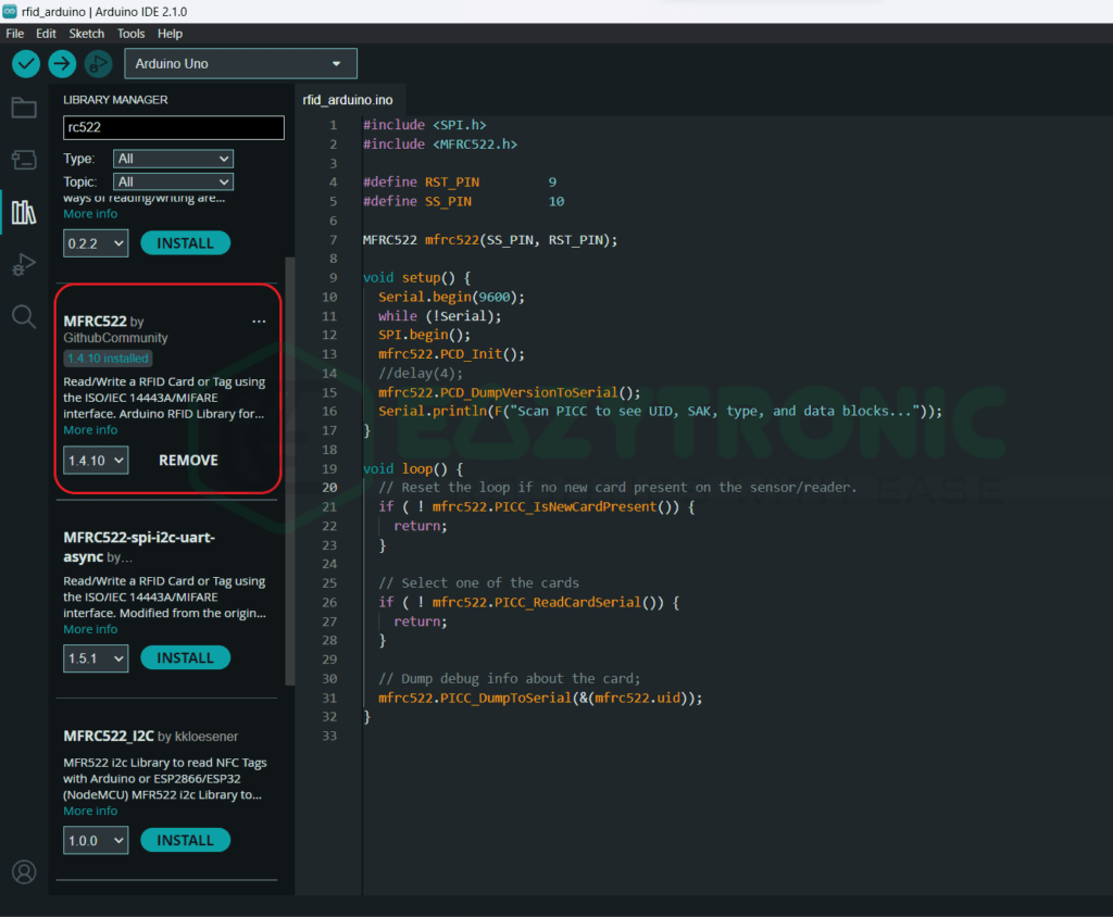
Code
This is an important section as from here all the parts related to code and explanation will proceed. Below is the code for the RFID module that works without any issues on my system. If you face any issues, first check the wiring, then comment down below if the problem still persists.
#include <SPI.h>
#include <MFRC522.h>

#define RST_PIN         9
#define SS_PIN          10

MFRC522 mfrc522(SS_PIN, RST_PIN);

void setup() {
	Serial.begin(9600);
	while (!Serial);
	SPI.begin();
	mfrc522.PCD_Init();
	//delay(4);
	mfrc522.PCD_DumpVersionToSerial();
	Serial.println(F("Scan PICC to see UID, SAK, type, and data blocks..."));
}

void loop() {
	// Reset the loop if no new card present on the sensor/reader.
	if ( ! mfrc522.PICC_IsNewCardPresent()) {
		return;
	}

	// Select one of the cards
	if ( ! mfrc522.PICC_ReadCardSerial()) {
		return;
	}

	// Dump debug info about the card;
	mfrc522.PICC_DumpToSerial(&(mfrc522.uid));
}
The above code works well with the RC522 RFID module and Arduino UNO. In addition to this, there are some limitations to some boards that I’ll mention further. The code is not as simple as others, so you need to read the explanation part. Copy the code and save it with some reasonable same so that you can remember. I have saved the code with the name “rid_arduino.ino”.
Explanation
Here comes the last and very important part. The code is somewhat hard to understand, so make sure to read the explanation properly. Moreover, only limited functions of the library are used for demonstration, so for complete information make sure to refer to the GitHub page of the library. You can also see some examples of different projects for reference.
#include <SPI.h>
#include <MFRC522.h>
First, we start by including some libraries in order to use the RFID module. These libraries are essential to include and can be different on different platforms. In the first line, we include the SPI library to enable the communication between RFID Module and Arduino. Make sure to use the SPI pins referred to above. However, if you are using other pins as SPI, then make sure to check the wiring and change the pins in the code.
In the next line, we include the library for RC522 RFID Module. This library can be easily included from Sketch Menu > Include Library. This library is the one I have used, if you are using some other library then make sure to check the libraries beforehand, or you might face some errors.
#define RST_PIN         9
#define SS_PIN          10

MFRC522 mfrc522(SS_PIN, RST_PIN);
Next, we define a pin for the miscellaneous pins of the RFID Module. MISO, MOSI, and SCK pins are by default assigned to the Module, so make sure to connect the correct pins. However, you can change the CS and RST pins according to your wish. Make sure, not to use the D10 pin for some other purpose while using the SPI communication. You can only use these pins either for CS pins or if using multiple SPI devices then use this along with assigning more.
Further, we create an object/variable for the RFID Module. This variable will now be used for every operation we want to perform. You can change the variable name according to your wish. The Syntax of the line is “MFRC522 <variable/object>(CS/SS pin, RST pin”. You don’t need to define the pins if you can remember the pins, as this also occupies the RAM of the Board.
void setup()
void setup() {
	Serial.begin(9600);
	//while (!Serial);
	SPI.begin();
	mfrc522.PCD_Init();
	//delay(4);
	mfrc522.PCD_DumpVersionToSerial();
	Serial.println(F("Scan PICC to see UID, SAK, type, and data blocks..."));
}
In the setup section, there are more statements than in the loop section. Here we define the lines that need to be run over once instead again and again. First, we begin the Serial communication, at the 9600 baud rate. You can change the baud rate according to your wish, but the most common one is 9600.
The next line is for the boards that are built upon ATMEGA32U4 as their main chip. What this line actually does is disable the flow of the program if the serial monitor is open. In Arduino UNO, there is a separate USB to Serial IC that does its job. Followed by this, we begin the SPI communication between the Arduino UNO and the RFID Module.
Further, we begin the MFRC522 RFID Module, this line makes some checks and makes the module ready to send and receive instruction from the Board. You can add some delay for this process to proceed further, as some boards might need it.
Lastly, we print some information about the reader onto the Serial monitor. This includes the version and firmware of the Reader. If you don’t want this, you can comment down this line. In the next line, we print the instruction on the Serial monitor, making it clear that the Module is ready to communicate with PICC cards.
void loop()
void loop() {
	// Reset the loop if no new card present on the sensor/reader.
	if ( ! mfrc522.PICC_IsNewCardPresent()) {
		return;
	}

	// Select one of the cards
	if ( ! mfrc522.PICC_ReadCardSerial()) {
		return;
	}

	// Dump debug info about the card;
	mfrc522.PICC_DumpToSerial(&(mfrc522.uid));
}
This is the last section of the code. Here we write the code that repeats throughout the time. First, we check for the condition of the card placed in front of the Module is the same or different. If the card is different, then it will iterate the condition without moving further.
However, if the condition is false, then comes the next condition. This condition is to select one card if multiple cards are placed in front of the Module. It selects one of the cards, reads its UID, and stores it temporarily. This UID can be accessed from &(<varible>.uid). If you know Pointer in C then you can understand what it does.
In simple words, <variable>.uid stores the address of the variable that stores the UID of the card. You can access the value by simply putting & the symbol before it that corresponds that we want the value that is associated with that address.
In the last line, we print details about the card that matches the UID stored in the temporary variable. You can also replace the &(mrfc522.uid) with the UID of the card if you know the UID. Else, it is recommended to let it be as it is.
With this, we have completed a demonstration of the RFID Module with Arduino UNO. If you found any issue regarding the code then comment down below, and I’ll make sure to resolve it ASAP.