
Sound sensor, with Arduino UNO, is one of the important sensors you should practice. Welcome back guys, I’m back with another interesting article in Arduino Series. The sound sensor is significant as it gives your project or development board a sense to hear sounds. Not like humans, but the sound frequency of a certain range that is amplified to an extent can be detected. As we’re using Arduino UNO, a basic development board, therefore there are no such interfaces like I2S that is capable of encoding and decoding sound. With this, let’s dig deeper into this.
Sound Sensor and Arduino in Brief
Sound sensor
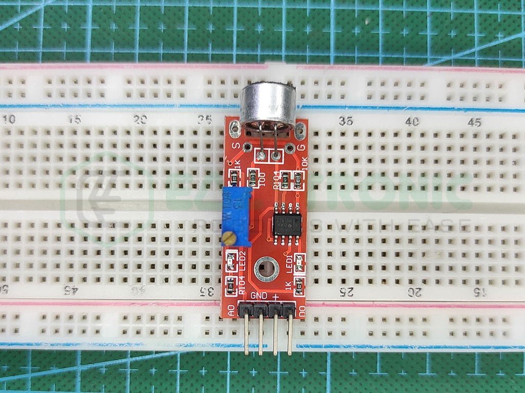
This sensor is built using a condenser microphone and an Op-Amp to detect certain sound frequencies. There are many sound sensors and microphones that you can make into use. However, for demonstration purposes, we’ll be using the very basic one.
The IC used in this sensor is LM393, which is basically a Dual-Comparator. If you are wondering, how would a comparator work to amplify the sound? Then let me clarify that there are many ways to reach a point, so don’t worry about it.
The condenser microphone used here detects the sound and converts it into an electrical signal that is compared with the reference voltage set on the other side of the comparator. Finally, on the output side, the voltage signal is the same as that of the signal coming from the microphone. However, on the Analog output, the signal is continuous while on the digital output, the 2nd part of the comparator delivers the output.
This sensor has a logic level the same as that of the input voltage. Like if you give 5V to the Vcc pin then the logic level is 5V and vice versa. Also, there is an attached schematic for a clear understanding.
Arduino UNO
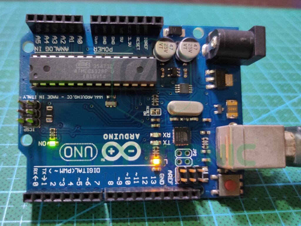
Arduino UNO is the most well-known microcontroller among newcomers. This development board is inexpensive, readily available, and provides plenty of functions for a beginner to get started. The majority of the components are DIP versions, and the board is the ideal size. Therefore, it offers a good probability of being repaired if something goes wrong.
The ATMEGA328PU IC, a DIP-28 Package microcontroller, is used as the primary building block of the Arduino UNO Board. It is an 8-bit CMOS microcontroller with an AVR platform that can run at a frequency of 16MHz. When compared to other microcontrollers in the same price range, this speed is poor. However, this is also excellent and faultless for a beginner.
The Ram and storage part is next. The Arduino UNO comes with 2 KB of SRAM, which can handle a lot of data for most projects. The 32 KB of SPI Flash storage that comes with it can be increased with the use of external SPI memory. Additionally, it has 1 KB of EEPROM memory, which is able to retain data until the user removes the board.
The power and pins part comes last. There are 23 I/O pins available on the Arduino UNO board in total. There are 13 digital pins in all, and the code can control them. Six of these digital pins, known as PWM pins, are also programmable. Additionally, it offers 6 Analogue pins with a resolution of 10 bits. SPI, I2C, and serial data connections, among others, are all available.
For various devices, the board offers 3.3V and 5V power supplies.
Material Required
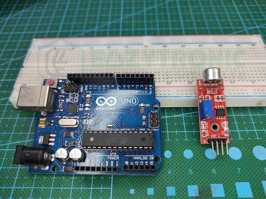
- Arduino UNO
- Sound sensor
- Breadboard
- Jumper wires
- A system to program Arduino UNO
Fritzing Schematic
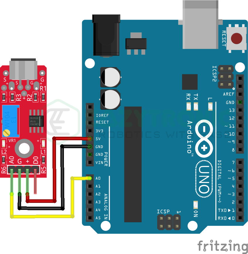
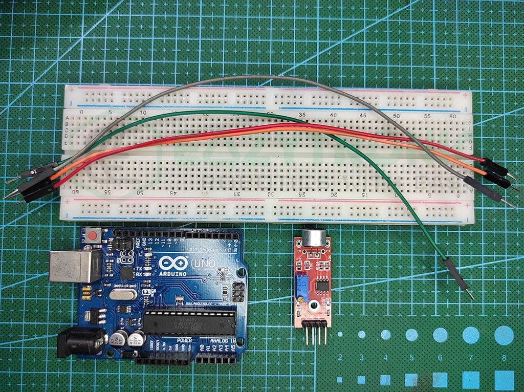
Wiring
| Arduino UNO | Sound Sensor |
|---|---|
| 5V | Vcc/+ |
| GND | GND/- |
| A0 | A0 |
| D3 | D0 |
Programming Arduino
For programming the Arduino, you need to hook up the Sound sensor and Arduino NO as described above. Like in the last article, MQ-3 Sensor, we’ll be using both types of code and demonstration to explain its working. However, for both cases, you need Arduino IDE to program for that, make sure to download the latest version from their official website. A tutorial for beginners to explain the installation process is explained in the introductory article of Arduino, make sure to read it. On the other hand. If you have already downloaded it, make sure to update all the board definitions and libraries to avoid any errors during compilation. With this, let’s proceed further.
Code
The code below is the same as the MQ-3 sensor program, the difference is just we’ll be using a different variable to store pins for the sound sensor. If you have already read that article, you can use the same code as the working same. For those who are new, they can read further for an explanation.
#define sound A0
//#define sound 3
//#define LED 13

 void setup(){
   Serial.begin(9600);
   pinMode(sound, INPUT);
   //pinMode(LED, OUTPUT);
 }

 void loop(){
   Serial.println(analogRead(sound));
   /*
   if(digitalRead(sound==HIGH){
     digitalWrite(LED, HIGH);
   }
   else{
     digitalWrite(LED, LOW);
   }*/
 }
The code above is in the combined form, to means both analog and digital output is written in the same file. However, based on your need, you can comment on the lines for specific versions. But before that, make sure to save the code with some meaningful name. I’d recommend you save it with “sound_sensor_with_arduino”. You can change the name but make sure not to use any spaces as it’ll show an error.
Explanation
Now we’ll start our explanation section. This is the Analog code explanation, for digital code explanation scroll below.
#define sound A0We first define the pin to which the Analogue Out pin of the Sound sensor is connected to the Arduino UNO’s A0 pin. You can also adjust the pins to suit your preferences. However, I’ve gone with A0 for the most typical example. Additionally, you might put the pin in an int variable; but, the define macro argument offers advantages that a person from a programming background would understand.
void setup()
void setup(){
   Serial.begin(9600);
   pinMode(sound, INPUT);
 }
We will merely start the Serial communication and set the pin mode for the pin to which the Sound sensor is connected in the setup section because there isn’t much else to write. The serial transmission operates at a 9600 baud rate, but you can alter it as you choose. You can use this value to display pixel LED waveforms or something interesting, that I’ll show in future articles.
void loop()
void loop(){
   Serial.println(analogRead(sound));
 }
We only need to print the value that the sensor is giving us in the loop section. We have already started the serial communication for this. Now, all we need to do is type Serial.println(<value>); to print the value. I made a small adjustment to the code, substituting the analogRead function for value. The value returned by this function is in integer format. Because of this, there is no need to store the value and provide the board with an extra variable to store.
Digital Value Code Explanation
//#define sound 3
//#define LED 13
If you’re copying it from here, be sure to comment out these lines. The pins on which the sensor and LED are connected are described in the first two lines. We must use the digital pin because we are using the digital value from the sensor. I’ve used the Arduino UNO Board’s built-in LED as the LED. The pin can be changed, and the desired pin can be used to connect an external LED.
void setup()
 void setup(){
   //pinMode(sound, INPUT);
   //pinMode(LED, OUTPUT);
 }
Since we’ll be using the LED to indicate whether alcohol is present, we don’t need to start the serial communication in the setup step. For this, we must specify the pin mode for the pins that connect the sensor and LED. We need to designate the sound sensor pin as the input, whereas you need to define it as an output pin for the LED.
void loop()
void loop(){
   /*
   if(digitalRead(sound)==HIGH){
     digitalWrite(LED, HIGH);
   }
   else{
     digitalWrite(LED, LOW);
   }*/
 }
We’ll use the condition in the loop section to determine the MQ-3 sensor’s current status. I’ve applied a straightforward if…then…condition to this. When the sensor’s output signal is HIGH, we turn on the LED at pin 13 as well. In contrast, if the sensor’s input is LOW, the LED will also be LOW. Depending on your preferences, you can also set different statements in the if and else conditions.
With this, we have completed the demonstration of the Sound Sensor with Arduino UNO. If you need assistance with anything, just comment below.