Hey Folks, we’re back with another interesting article, Blynk with HC-SR04 based on IoT. HC-SR04 is one of the basic sensors, it can be interfaced very easily with almost every development board out there. We have demonstrated its interfacing with many development boards, links to which are provided below. Today we’ll demonstrate its interfacing with NodeMCU and try to display its value on the Blynk App just in the case of Ir Sensor. For an introductory article and more description about the HC-SR04 and NodeMCU head over to their respective articles. So, without wasting any time, let’s start today’s discussion.
HC- SR04 and NodeMCU in brief
HC-SR04
HC-SR04 is one of the best sensors for measuring distance, however, it comes with certain limitations. Besides this, it is cheap and easily affordable, and programmable with different boards. Moreover, if you want to read about HC-SR04 in detail, then here is the link to the article, you can read about its building in detail there. HC-SR04 is quite popular as it can measure distance up to some accuracy despite its flaws. This sensor has 4 pins, two power pins, and two communication pins. There is also another model that comes with 3 pins, two power pins, and a ping pin, in this only a single pin is used for communication.
This sensor is built out of two MAX232 driver ICs for driving the ultrasonic transducers. Paired with an LM324 Op-Amp for amplifying the incoming signal. All these processes are controlled by an 8-bit Microprocessor, EM78P153. The circuit is quite hard to replicate in the same compact size. However, if you like to replicate it, the schematic and other details are mentioned in the article on HC-SR04. On the other hand, if the sensor gets damaged, there is negligible scope for repair. As the components are mostly SMD and are hard to repair for beginners.
NodeMCU
NodeMCU is one of the most popular development boards among beginners. Due to its compact size and support, for easy to program interface like Arduino IDE. Besides, this comes with some rather powerful specs and features that can make a huge difference from other development boards at the same price. This board is manufactured by Espressif Systems, and along with this they also manufactured many other boards. ESP8266 aka NodeMCU packs with a Tensilica Xtensa LX106 32-bit RISC Microprocessor that is capable of running RTOS. Moreover, it can operate on a variable frequency of about 80MHz-160MHz. Regardless of these high-performance specs, it comes in a rather small size that is comparable to the size of your thumb.
In addition to this, it comes with 128 KB of SRAM that is capable of running some nice powerful lines of code. Moreover, it is paired with 4 MB of SPI FLASH ROM Storage, this is quite a handful for most of the projects. In addition to this, it also comes with an 802.11b/g/n Wi-Fi Transceiver. However, it doesn’t support Bluetooth like its other version, which does. Now comes the main thing, the pins. NodeMCU has enough pins for normal use, but for tasks like using analog sensors in a bunch, it creates a problem as there are not enough analog pins on it. Overall, if we see this board is most suitable for beginner use, due to its low cost and better features it is highly recommended.
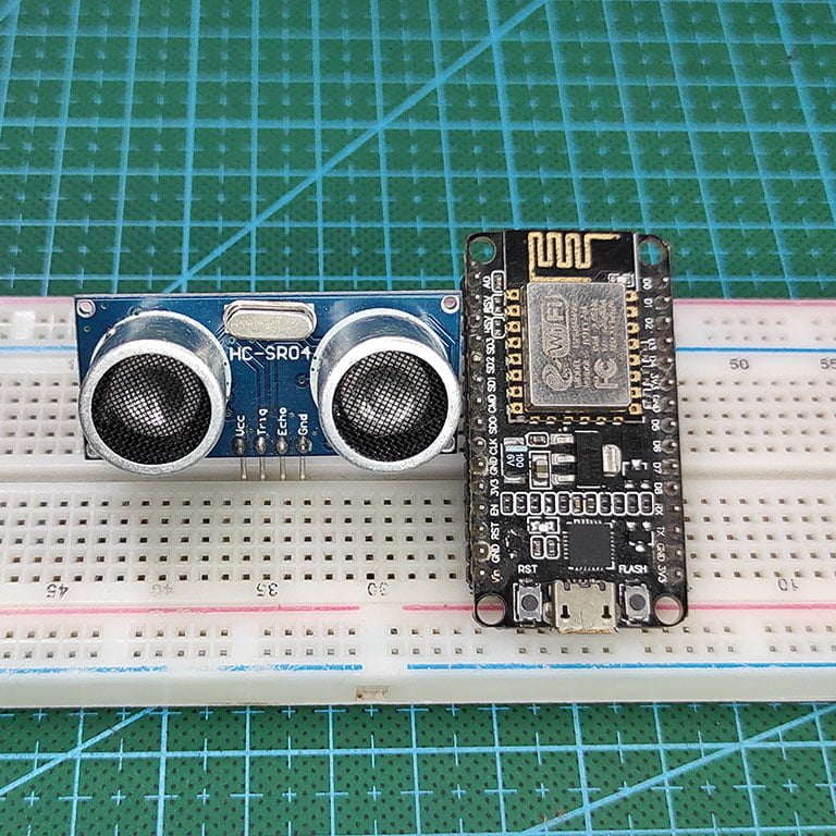
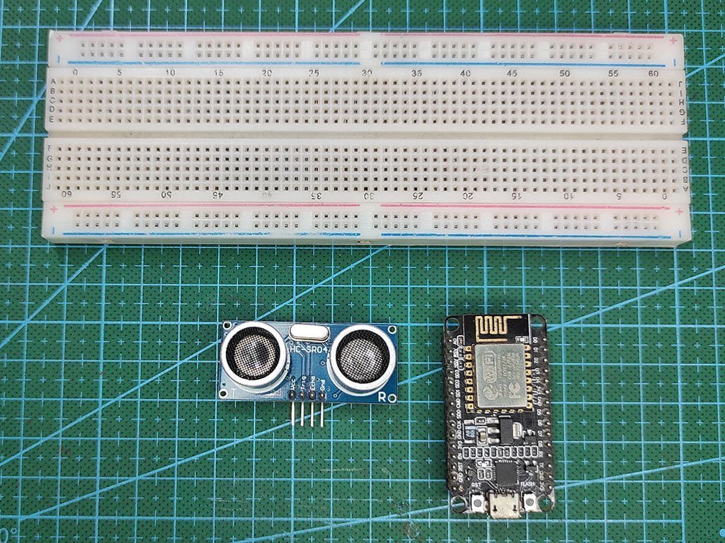
Material Required
Listed are some of the materials that are required for the demonstration of the interfacing Blynk with the HC-SR04 sensor. All the components are easily available either in the local or online market.
- NodeMCU
- HC-SR04
- Jumper Wires
- Breadboard
- Object for detection
- Blynk Interface for display of status.
Fritzing Schematic
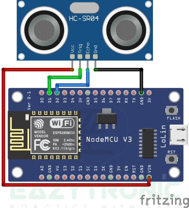
Wiring
| HC-SR04 Pin | NodeMCU |
|---|---|
| Vcc | VIN |
| TRIG | D1/GPIO5 |
| ECHO | D2/GPIO4 |
| GND | GND |
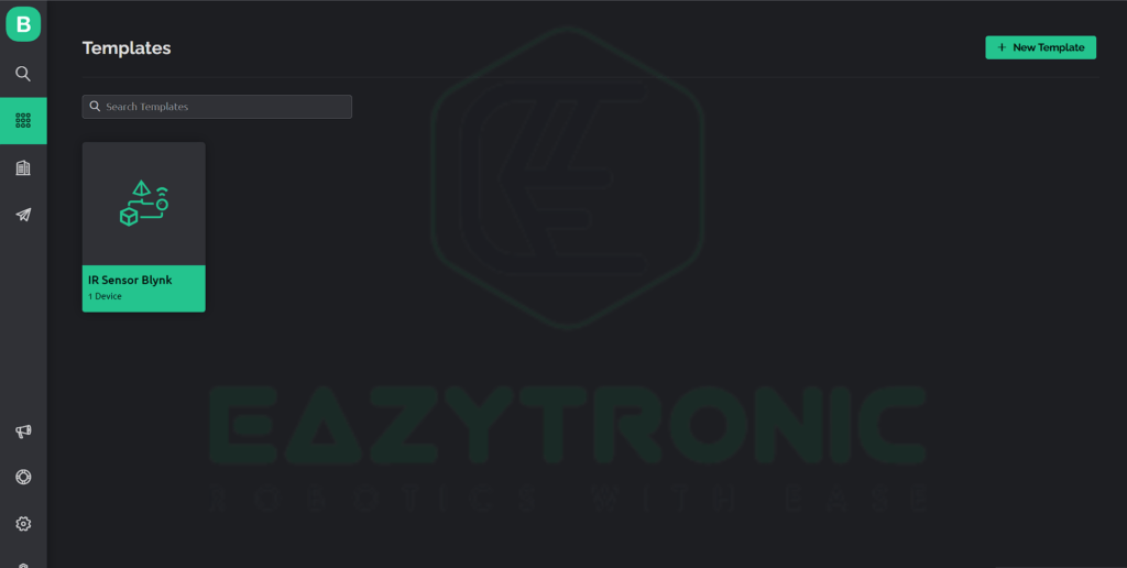
Designing Blynk Interface
For designing the blynk interface for Blynk with HC-SR04, we’ll be using the same template and device as that of the IR Sensor with Blynk. I have explained all the steps in detail in the that article. Make sure to read that to understand it well. Moreover, I have marked the section specifically for designing templates and devices. Also for web dashboard and mobile dashboard. Do remember that you’ll be needed an account on the blynk server to do this. So make sure either you make one or if you have one then you must be logged in.
Web Dashboard
For designing a Web Dashboard, make sure to follow the steps mentioned below. To make it easy, I have made them in bullet points.
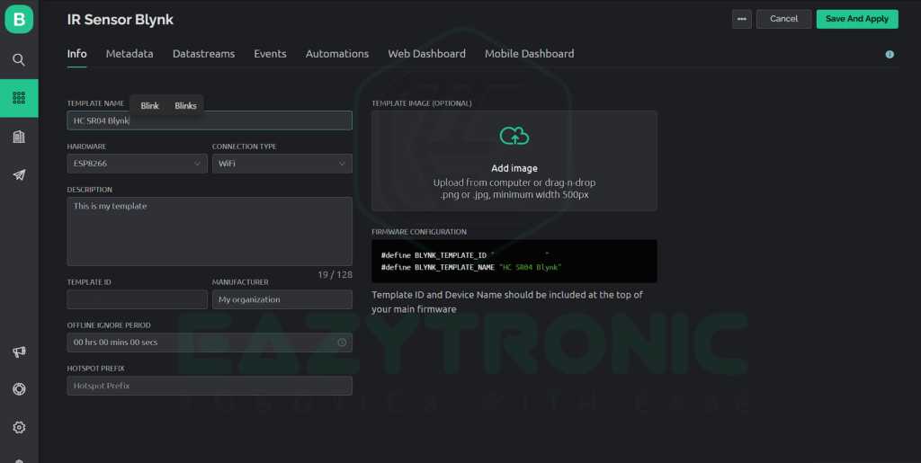
- First login to your account and wait until the home page opens. The home page will be your dashboard home window, from there open the template section to modify it.
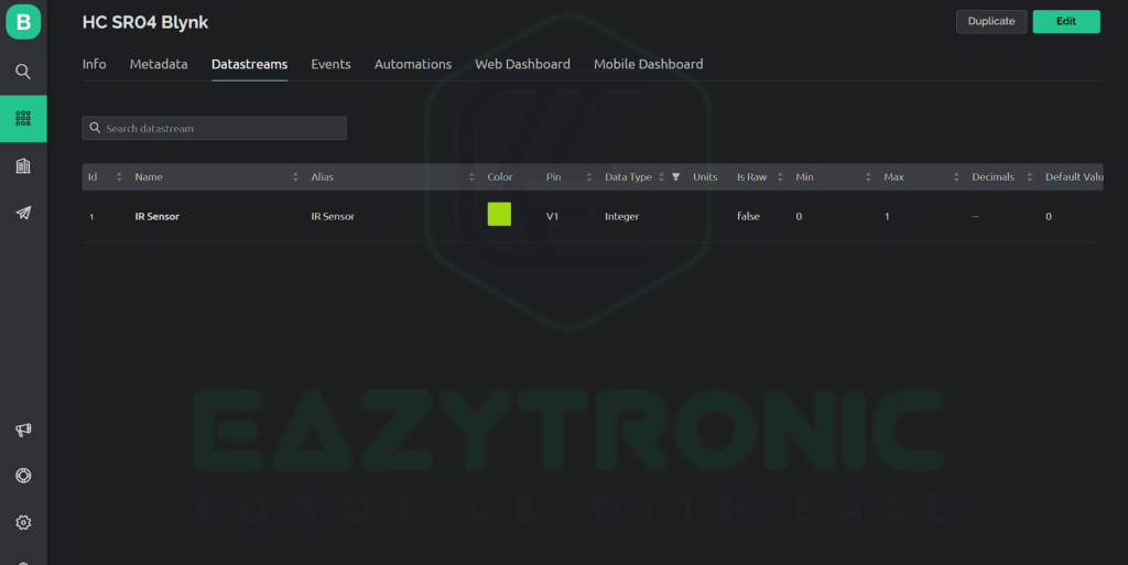
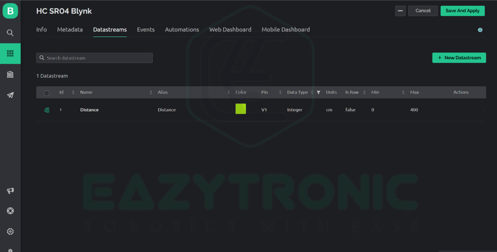
- Next, head over to the Datastreams tab to either modify it from the previous demonstration or create a new one like this one. Once you have modified the datastream you can now move to the web dashboard to modify it.
- Click on the Web Dashboard tab and then click on edit, if you have previously made something on it. Otherwise, create a new widget according to the steps mentioned in IR Sensor with Blynk.
- Select the widget and click on the gear icon to modify it. Below is the reference image of the settings of the widget. Change all the settings that are not crucial according to your choice.
- However, keep in mind that the device and template both are same also same for the data stream. With this done, we are good to proceed to the next part.


Mobile Dashboard
Now as we have done the web dashboard we can now design a mobile dashboard to see distance value and operate it via mobile phone.
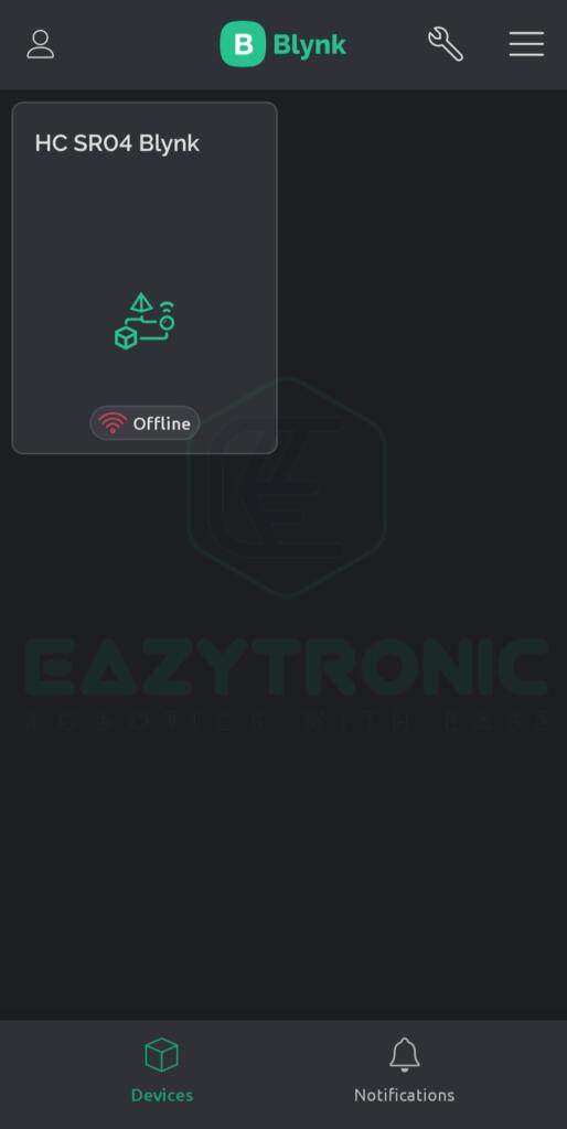
- First, make sure that you update your app as recently few changes need to be taken effect after the update. Once you are ready, open the app and wait for it to refresh.
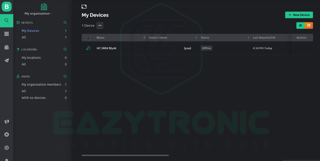
- If you are opening the app for the first time then you might not see anything rather than just a blank screen and add a device notification. So first log in to sync your device and templates.
- However, if you are a regular reader then you must have known we have already created a template and device that we’re using. To keep things simple, we’ll be using the same template as the previous one.
- Therefore, we just need to edit the name and some other settings. I have attached some reference images below for you guys to help. On the other hand, the steps are explained below.
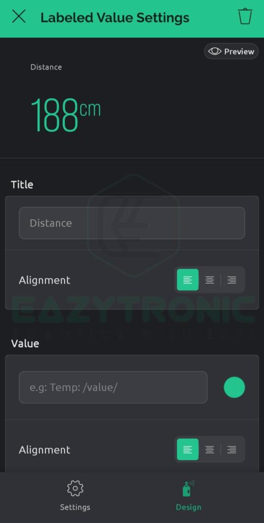
- First, open the template and then click on the wrench icon, a new window will open now select the existing widget and change some settings.
- As you can see, the datastream has already been updated, and we can continue only by changing the widget name and color as you wish.
- Once you are done, you can now close the app and focus on programming the development board.


Programming NodeMCU
Once you have completed all the steps told above, you can now program your NodeMCU or any other series of the board for the same purpose. In this demonstration, I’m currently using both the official and clone of NodeMCU to test the code. However, if you have any one of those, then it’s also ok. I’ll make sure that the code works fine without any issues. So without wasting any time, let’s continue forward.
Code
#define BLYNK_TEMPLATE_ID "YOUR TEMPLATE ID"
#define BLYNK_DEVICE_NAME "YOUR DEVICE NAME"
#define BLYNK_AUTH_TOKEN "YOUR AUTH TOKEN"
#define BLYNK_PRINT Serial

#include <ESP8266WiFi.h>
#include <BlynkSimpleEsp8266.h>
char auth[] = BLYNK_AUTH_TOKEN;

#include <Ultrasonic.h>
Ultrasonic sensor(5,4);
int distance;


// Your WiFi credentials.
// Set password to "" for open networks.
char ssid[] = "Wi-Fi SSID";
char pass[] = "Password";

BlynkTimer timer;

void myTimerEvent(){
  Blynk.virtualWrite(V1,distance);
}

void setup()
{
  Serial.begin(9600);
  Blynk.begin(auth, ssid, pass);
  timer.setInterval(100L,myTimerEvent);
}

void loop()
{
  distance = sensor.Ranging(CM);
  Serial.println(distance);
  Blynk.run();
  timer.run();
}
This is the code for Blynk with HC-SR04, there are some slight changes in the previous code. Therefore, make sure to read the explanation part for a clear understanding. Moreover, you can save the code with any name but for easy recognition save it with a name easy to understand.
Explanation
Now we come to the explanation part, here we’ll be discussing every line and making sure you’ll be able to modify the code as you wish. With this, let’s begin.
#define BLYNK_TEMPLATE_ID "YOUR TEMPLATE ID"
#define BLYNK_DEVICE_NAME "YOUR DEVICE NAME"
#define BLYNK_AUTH_TOKEN "YOUR AUTH TOKEN"
#define BLYNK_PRINT Serial
First in the starting as always we define some crucial information regarding our template and device. These include Template ID, Device Name, and Auth Token. Make sure if you are using simple code Like I’m using then you can use only AUTH TOKEN as it was only necessary. However, if you are using the Edgent code, then you’ll also be needed with template ID and device name. Along with this, we also define Blynk Serial that prints every action NodeMCU perform after the code start.
#include <ESP8266WiFi.h>
#include <BlynkSimpleEsp8266.h>
char auth[] = BLYNK_AUTH_TOKEN;
Next, we include some libraries to enable support for Blynk IoT functionality. These two libraries include almost all the required functions that are needed to make code usable and executable. Also, we create a variable character array that stores all the contents in the string, followed by equals to sign. This variable will be used further in the code for some very important tasks.
#include <Ultrasonic.h>
Ultrasonic sensor(5,4);
int distance;
Next, we initialize the library for ultrasonic sensors, there are many libraries for HC-SR04 Ultrasonic which you can find online. However, they need certain adjustments to work perfectly. I have mentioned all this in a dedicated article, More in HC-SR04. In the next line, we create an object that points to the pins on which the TRIG & ECHO pins of the sensor are connected. In addition to this, we also make a variable that stores the distance value from the sensor.
char ssid[] = "Wi-Fi SSID";
char pass[] = "Password";

BlynkTimer timer;
Further, in the code, we store your Wi-Fi credentials in the SSID and pass character arrays. Followed by this, is the timer object that will update the values on the blynk server at regular intervals.
void setup()
Serial.begin(9600);
Blynk.begin(auth, ssid, pass);
timer.setInterval(100L,myTimerEvent);
In the setup section, we write those instructions that need to be run once during the runtime. First, we start the serial communication at a 9600 baud rate. Next, we begin the communication with the Blynk Server by making the connection to the server. For this purpose, we use the auth token stored first in the auth token array. Followed by the Wi-Fi, make sure you give the Wi-Fi details of a 2.4GHz Wi-Fi connection. I have both types of Wi-Fi connection at my place, but my NodeMCU didn’t connect to my 5GHz Wi-Fi connection. Therefore, I always make certain that my code contains my 2.4GHz Wi-Fi details. Maybe this is because of the older Wi-Fi protocols used in older models.
As a result, I always advise you to use your 2.4GHz Wi-Fi SSID and password, as it might lead to some connection problems in some cases. Nevertheless, if you have other modules that can connect to 5.0Ghz you can use that board and for support ask me in the comment. The last line is for setting the frequency of value updates. If you have read my previous article, then you might know that I have highlighted this step. But in the previous one, I made this line comment as it was not needed. But after the update, there is a need to adjust the frequency. Therefore, I have included and explained it here. The syntax of this line is timer.setInterval(time(in ms)L, function call name);. Hence, if we see the frequency of this function is 10 times per second, which is the maximum limit of the free account
void loop()
distance = sensor.Ranging(CM);
//Serial.println(distance);
Blynk.run();
timer.run();
Now comes to the loop section, this section is very important. Here we write the main code that makes all the sensors and the Blynk server works. Although for beginner’s articles, the codes are very simple, for advanced code there can be many complications. However, here we’ll be explaining all the lines very clearly so that you can be able to modify the code on your own. In the first line, we read the distance from the HC-SR04 sensor and stored it in the distance variable. The next line is for testing only, you can uncomment it if you want to know the distance and print it on the Serial monitor. The next two lines are essential, precisely the next line is compulsory for every blynk code.
Blynk.run() line runs all the processes to fetch and push the data from and to the Blynk server. Followed by this is the line to run the timer function that updates and writes the distance value to the virtual pin we created on the web and mobile dashboard. However, if you are not using the timer function of the Blynk library, you don’t have to use it. This line will shift the flow of the program to the function value that you want to run here, aka the timer function. The timer function we have created will now execute all the instructions we have written inside that.
Timer Function
Blynk.virtualWrite(V1,distance);This is the last part of the code, it is very important as from this part the value gets updated on the server. In this section, whatever lines of code we write, it’ll get updated at the frequency we have defined previously. Here, in Blynk with the HC-SR04 article, we just have to update the distance value, such that there is a minimum delay. There is only one line that is to update the distance, the syntax of this line is Blynk.virtualWrite(<virtual pin>, <value>);. Here, you have to write the correct virtual pin and value that you want to display on the server. If after writing all the code, it still doesn’t update, then make sure you are not sending more than 10 values per second. As that can also affect your program functionality.
With this, we have completed our demonstration of Blynk with HC-SR04. If you have any issues regarding understanding the code or some troubleshooting, comment down below. I’ll solve it ASAP.