
Hey Friends, welcome to PIR Sensor with Blynk IoT, another interesting article in the NodeMCU IoT series. Previously, we have demonstrated a few articles in this series that you can access via the category menu. There are many types of PIR sensors in the market, but the one we’re going to demonstrate is the HC-SR501 model. You can read the detailed article on this sensor, PIR Sensor. Moreover, if you want to read the detailed article on NodeMCU you can also read it NodeMCU. In today’s article, we’ll be demonstrating PIR Sensor with Blynk IoT App via NodeMCU. But before that make sure to read other articles, most importantly Introduction to Blynk as many points are explained there in detail. With this, let’s begin today’s course.
PIR Sensor and NodeMCU in Brief
PIR Sensor | HC-SR501
This is one of the simplest PIR sensors available in the market and is very beginner-friendly. PIR corresponds to Passive InfraRed, this is a more complex term to be called in daily life. The sensor that we’re using is HC-SR501, this is the simplest version available in the market. However, many advances and more technologically advanced sensors are also available like RCWL. Let’s keep them aside for some other time currently. This sensor has very few components. Moreover, you can also build this one yourself if you want with only a handful of components. The schematic of this sensor is available on the original article link. The schematic provided is made by reverse engineering an actual sensor. Therefore, it should work but if in some cases it doesn’t then let me know below.
If we try to open the sensor and see what is inside it, then there is a large Photo Diode that receives IR Light. You might be wondering how can IR light be used to detect motion. Well, if you know that every living being emits a small amount of heat from their body. The heat released has some light of wavelength falling in the IR Spectrum that can be detected by the Photodiode. If we take a look at some advanced sensors, those use microwaves for detection that strikes the object and comes back. If the transmitting signal strikes any obstacle, that will result in a change in the frequency of the transmitted signal.
NodeMCU
One of the most well-liked development boards among novices is NodeMCU. Because it has an easy-to-program interface like the Arduino IDE and is small in size. Also, this has some impressive characteristics and features that set it far apart from other development boards offered at the same price. Espressif Systems produced numerous additional boards in addition to this one, in addition to this board. Tensilica Xtensa LX106, a 32-bit RISC microprocessor that can run RTOS, is included in the ESP8266, also known as NodeMCU. Moreover, it may function at a changeable frequency between 80 and 160 MHz. Despite having such high-performance specifications, it is still just about the size of your thumb.
Also, it has 128 KB of SRAM, which can execute some great, powerful lines of code. Moreover, it is linked with 4 MB of SPI FLASH ROM Storage, this is quite a headache for most of the projects. Moreover, an 802.11b/g/n Wi-Fi transceiver is included. Nevertheless, unlike its other version, which does, it does not support Bluetooth. Now comes the major thing, the pins. NodeMCU has adequate pins for typical use, but for jobs like employing analog sensors in a bunch, it poses a difficulty since there are not enough analog pins on it. Overall, this board is ideal for novice users and is highly recommended because of its affordable price and superior features.
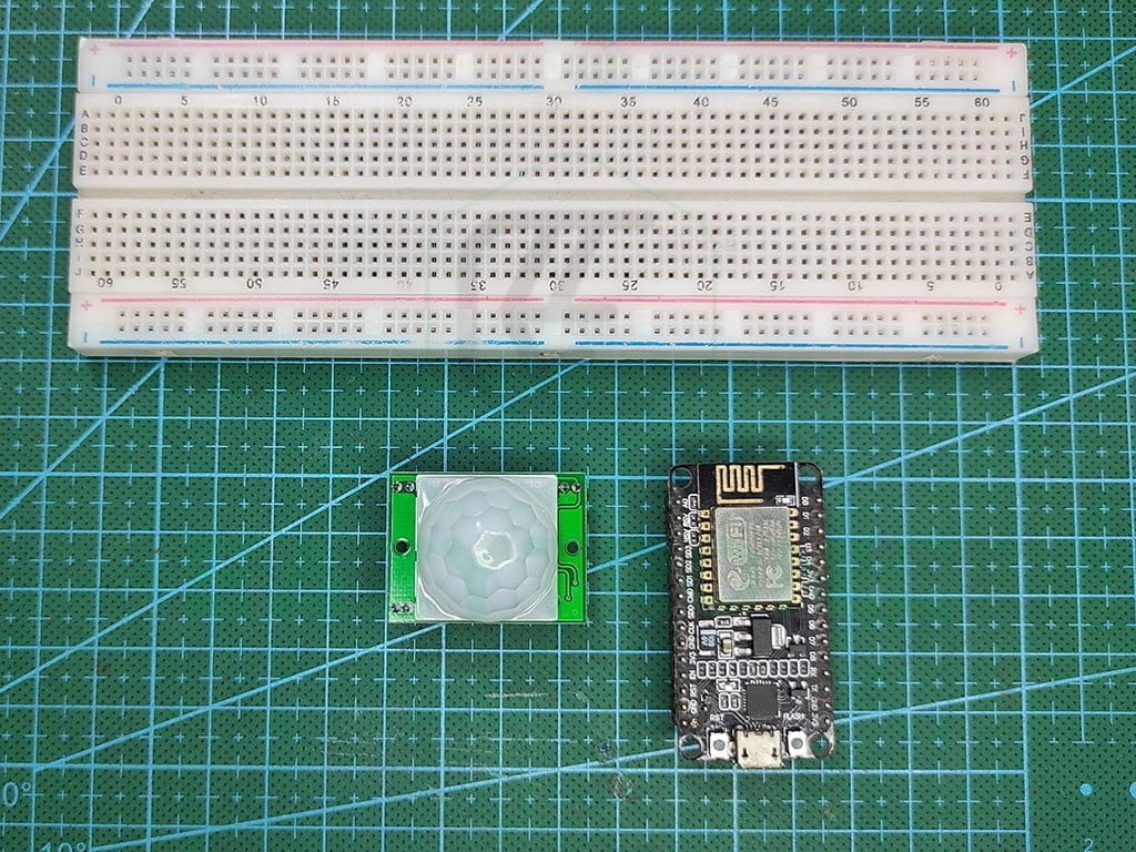
Material Required
The material required for the demonstration of this interfacing is very easy to collect, as it can be found easily in any offline or online market. Below is a list of some of the components that are required.
- PIR Sensor HC-SR501
- NodeMCU
- Breadboard
- Jumper Wires
- Blynk Interface on devices
Fritzing Schematic
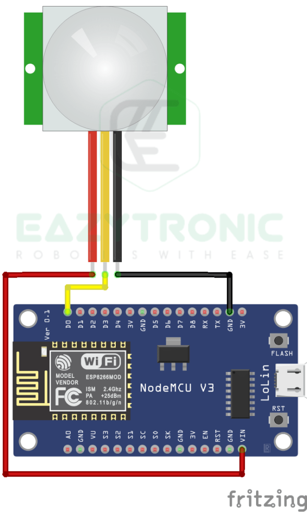
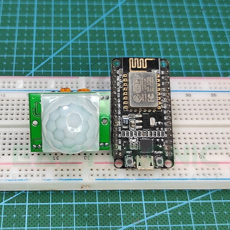
Wiring
| PIR Sensor | NodeMCU |
|---|---|
| Vcc | VIN |
| OUT | D0/GPIO16 |
| GND | GND |
Designing Blynk Interface
The Blynk Interface for this article will be somewhat different, as we’ll be not using the conventional label widget. Rather, we’ll be going to use the notification function to get the notification as soon as PIR Sensor detects the motion. Therefore, the code we’ll be using will be different from the recent two articles. I’ll try to explain the code in simple words so that you can easily modify it. However, it is advised to first check the functioning of the code and add flags in between to check the flow of code. With this, let’s start designing.
Web Dashboard
Updating the existing Web Dashboard can be sometimes confusing, so in order to remove this confusion, we’ll be designing anew from everything scratch.
- First visit blynk.cloud and log in into your account, If you haven’t created one then make one and log in.
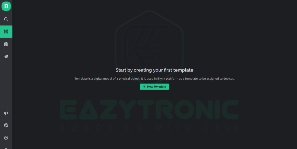
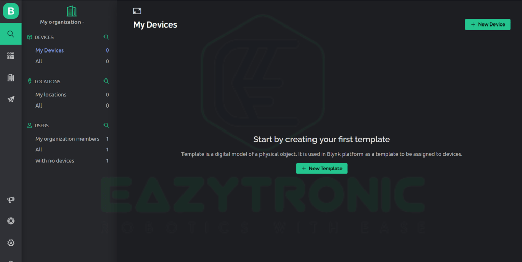
- Once you Log In a window similar to shown below will come, this is the dashboard of your account and from here we’ll be controlling our device.
- Now from the left side, click on the Templates icon, where we’ll create datastream and event. Moreover, we’ll also be editing the web dashboard from here.
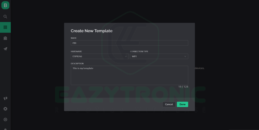
- Once you open the template section, you’ll be asked to create a new template, Click on Create Template button and fill the details according to your choice. A reference image is shown below.
- Click on Create Button on the bottom right of the window, once the template is created you have to ow click on it to open it. Once it is opened up, you can see various tabs on this page.
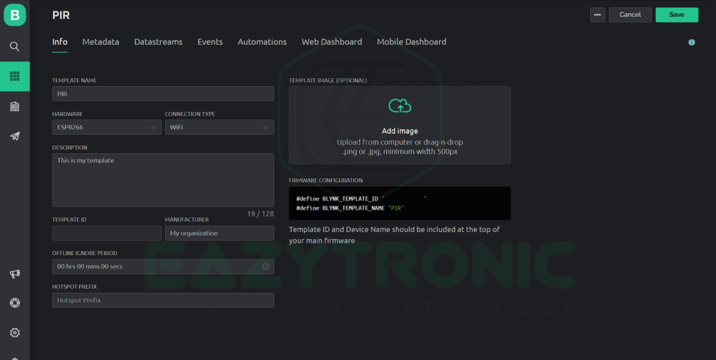
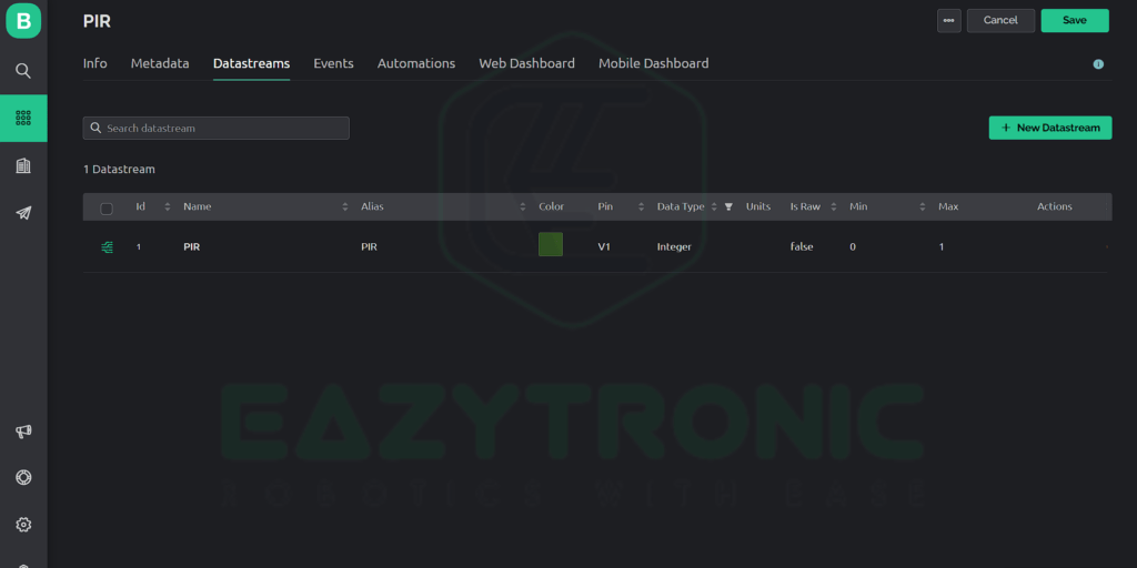
- On the info tab you get some crucial information, and I advise you to let this information be confidential. Now click on Datastreams tab to create one.
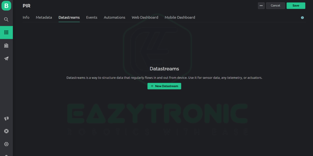
- You’ll be asked to create a datastream so click on create to do so. Here you’ll be asked for the type of datastream you want to create, select virtual pin and continue with it.
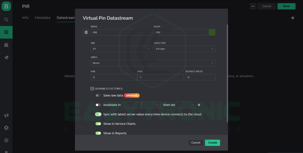
- Now fill all the necessary information as asked, you can change the name and other non-sensitive details, but sensitive ones must match like in the image shown below.
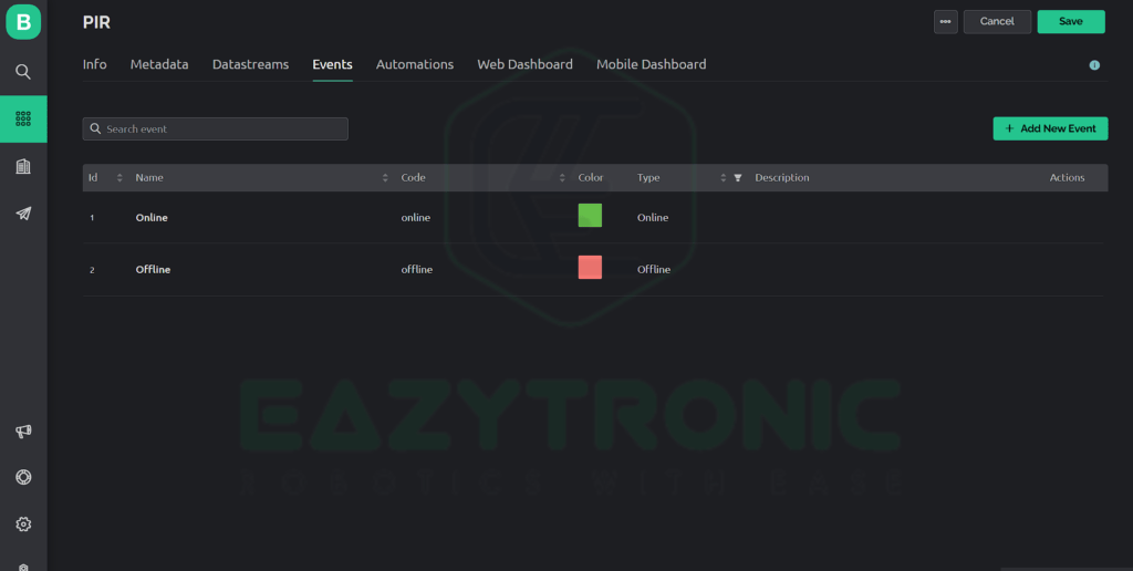
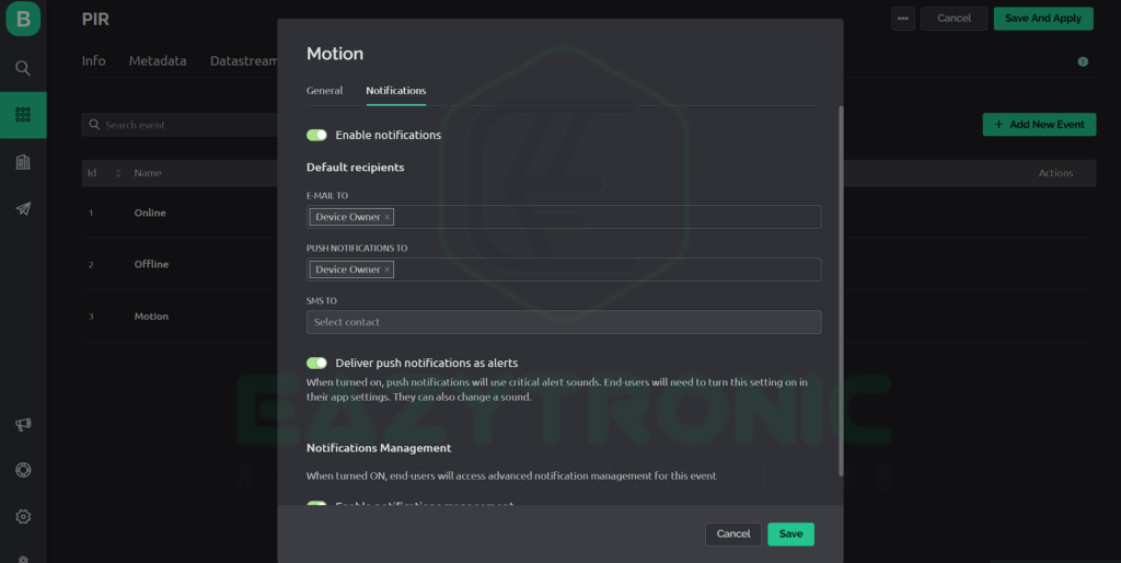
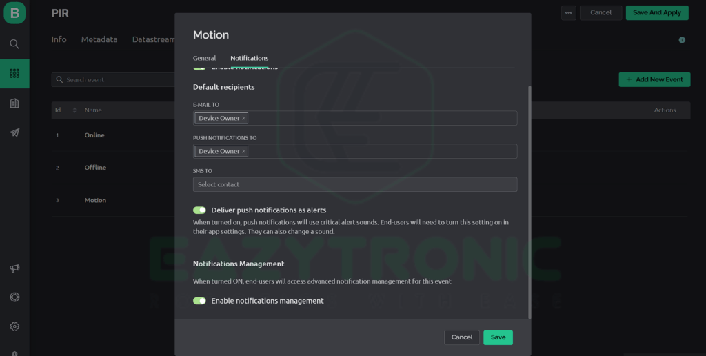
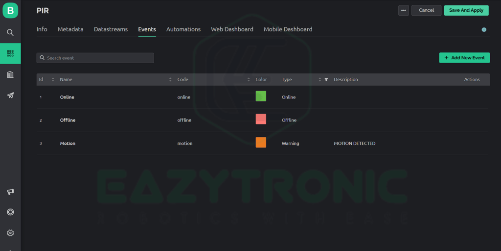
Creating Event
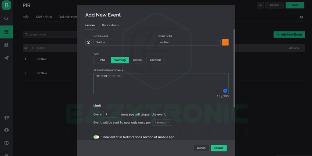
- Once you are done with creating a datastream, now we can proceed to the next step of creating an event. Switch to Event tab and create a new event similar to the image shown below.
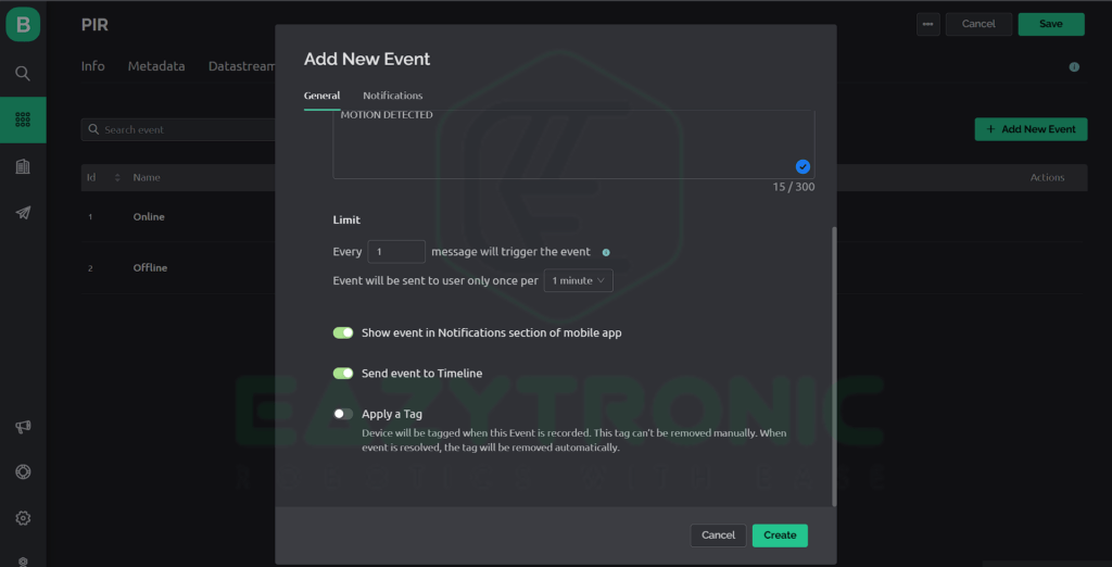
- To enable the notification, you have to enable those as in the steps shown below. The ones below are for reference for the free plan if you are using pro plan than you can change even more settings that you can ask me in comment section.
- Lastly, we have to create Web Dashboard for this switch to web dashboard and add an LED widget as shown in image. Edit this widget and select the datastream you just created.
Creating device
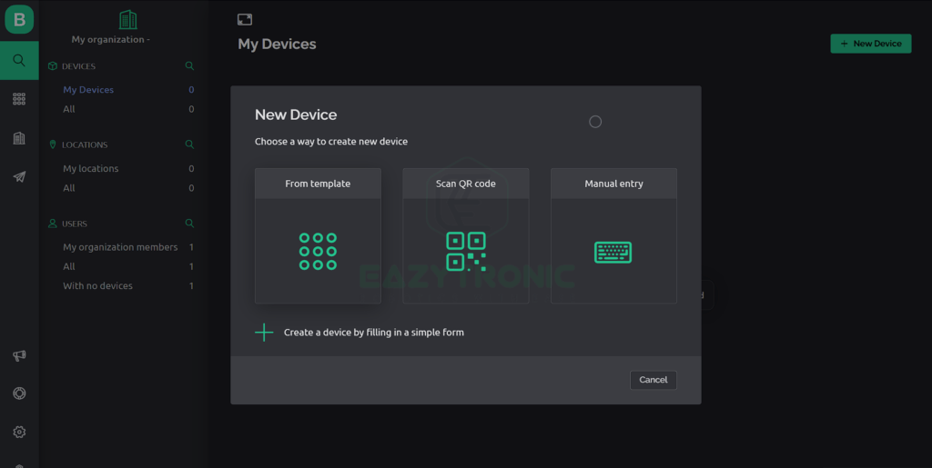
- Once you have done all the settings, from the left menu, select the search icon to go to devices tab. Once you reach there, you’ll be asked to create a device.
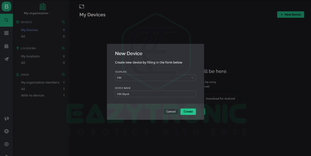
- Click on create device and select Create from template, now select the template you just created and click create. With we are done with everything that needs to be done on blynk.cloud portal. Now we have to set up the Mobile dashboard in the next step.
Mobile Dashboard
Designing Mobile Dashboard is rather very simple as we have done most of the steps on the cloud server.
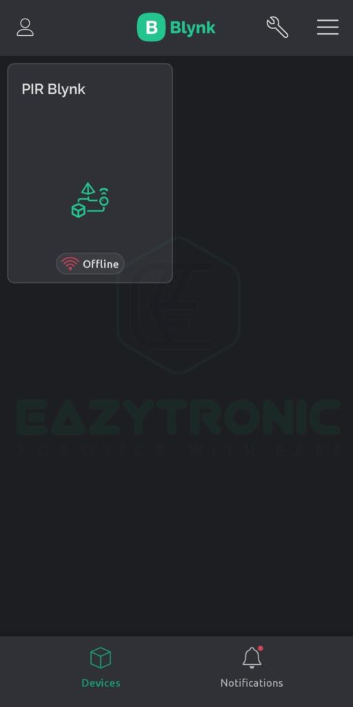
- Open the Mobile App and login with the same credentials that of the blynk.cloud server, also make sure to update the app to latest version if installed previously.
- Once you are logged in, refresh the app, a new device will automatically appear on your screen. This is the device we have just created on the web portal.
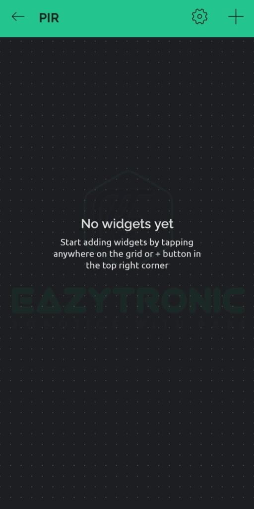
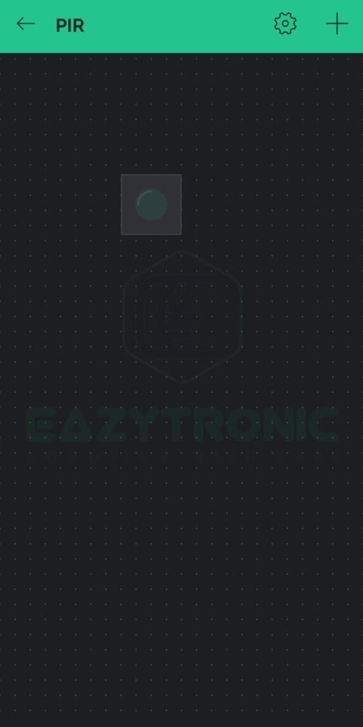
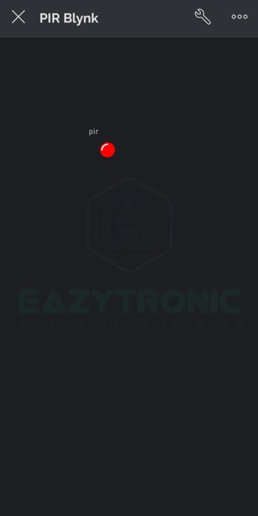
- Now click on it to open the device, once you enter into the device you’ll see a blank space. Here you have to add widget according to your wish.
- Now click o the wrench icon in the top right area a new window will open, in this you have to drag and drop the widgets. For this click on the Plus icon in the top right.
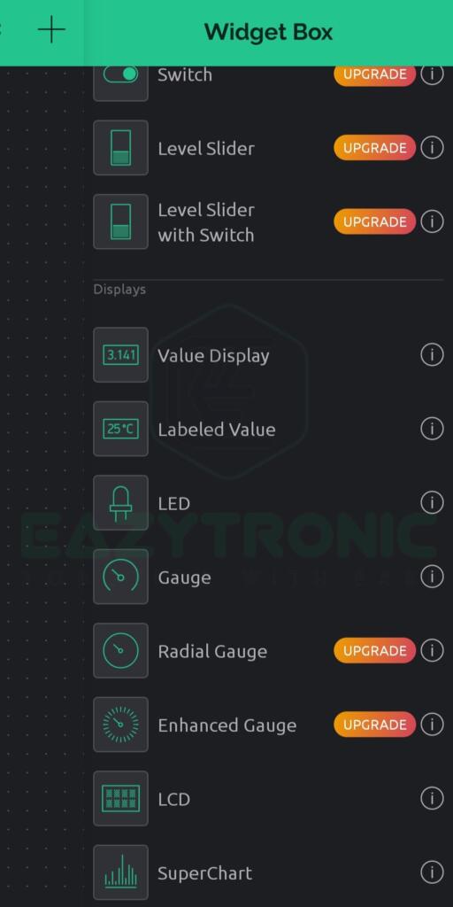
- A menu will appear from the left from there choose any widget of your choice, I have chosen led as an example. Change settings for this widget by simply clicking on it.
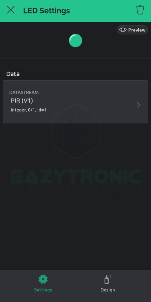
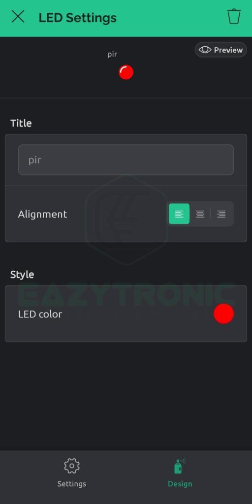
- Under Datastream section, change the datastream to the one you just created on the portal. Additionally, you can also change the design color of the widget according to your wish.
- Along with this, make sure you have notifications enabled for this app. For this move back to the main screen there, click on 3 dot icon adjacent to wrench icon, again click on the same icon on the new window opened.
- From there, select Notification settings and enable all the notifications. Once done, we can now program the NodeMCU using Arduino IDE.

Programming NodeMCU
For programming, the NodeMCU, make sure you have completed all the steps instructed before. Also make sure that all the libraries and board definition are up-to-date. The code provided further is optimized and works flawlessly for all models of NodeMCU i.e., original one and clone. The code is tested first and then provided, however, if there are conditions where code doesn’t work. Comment down below, I’ll see to it ASAP.
Code
#define BLYNK_TEMPLATE_ID "your template ID"
#define BLYNK_TEMPLATE_NAME "your template name"
#define BLYNK_AUTH_TOKEN "Your Auth Token"

#define BLYNK_PRINT Serial
#include <ESP8266WiFi.h>
#include <BlynkSimpleEsp8266.h>

int pir= 16;

char auth[] = BLYNK_AUTH_TOKEN;

// Your WiFi credentials.
// Set password to "" for open networks.
char ssid[] = "Wi-Fi SSID";
char pass[] = "Wi-Fi Password";


BlynkTimer timer;

void motiondetect(){
  if(digitalRead(16)==HIGH){
    Blynk.virtualWrite(V1,1);
    Blynk.logEvent("motion","Motion detected");
  }
  else{
    Blynk.virtualWrite(V1,0);
  }
}

void setup()
{
  Serial.begin(9600);
  Blynk.begin(auth, ssid, pass);
  timer.setInterval(1000L,motiondetect);
  pinMode(16, INPUT);
}

void loop()
{
  Blynk.run();
  timer.run();

}
Explanation
This is the most important section of the article, here I’ll explain every section of the code in segments and with complete detail. Make sure to read it in case you need to modify the code according to your wish.
#define BLYNK_TEMPLATE_ID "your template id"
#define BLYNK_DEVICE_NAME "your device name"
#define BLYNK_AUTH_TOKEN "your  auth token"
First, we declare a few crucial lines of code in the program. These three lines—Auth Token, Device ID, and Template ID—are crucial for differentiating between your various projects. Also, these three pieces of information are essential because, without them, NodeMCU and Blynk Server cannot communicate with one another. Additionally, if another person knew these 3 elements, they might simply control your project. Thus, it is best to keep them a secret and avoid making them publicly available because doing so could put your project at risk.
#define BLYNK_PRINT Serial
#include <ESP8266WiFi.h>
#include <BlynkSimpleEsp8266.h>
We then add a few libraries that are necessary for the application to run and compile. Also, these libraries can vary from board to board, so double-check the appropriate libraries for your board. Read the associated board article using the Blynk App for more details.
int pir= 16;

char auth[] = BLYNK_AUTH_TOKEN;

// Your WiFi credentials.
// Set password to "" for open networks.
char ssid[] = "Wi-Fi SSID";
char pass[] = "Wi-Fi Password";


BlynkTimer timer;
We start by defining the pin that will be used to attach our IR sensor to the circuit board. We then set up a few variables to store data that will later be used by the application. These variables can vary based on the needs of the user, and changing their names also has no bearing on anything. Nonetheless, we have specified a few key terms in the last three lines. Lastly, we define a timer object that we will use later.
void setup()
Serial.begin(9600);
Blynk.begin(auth, ssid, pass);
timer.setInterval(1000L,motiondetect);
pinMode(16, INPUT);
In the setup section, we begin will our all-time favorite Serial.begin(9600). This line begins the serial communication between the microcontroller and the IDE. After this we begin the communication with the server, for this, we need those 3 crucial pieces of information. Precisely, we only require Auth Token because we are using the simple code, not the Edgent one. For this, the SSID and Password of your Wi-Fi connection are required, make sure to put the correct one. At this point, I want to point out one thing, NodeMCU boards are only capable of scanning 2.4GHz Wi-Fi signals. I don’t know about the newer models, but the one I have cannot connect to a 5GHz connection.
To solve this issue, make sure to use a Wi-Fi connection of a suitable frequency. You can see the status of the connection in the Serial monitor for more information. Once the connection is made, it’ll display the ping of your device from the server that confirms the connection is successfully made. In the next line, we set the frequency of running the timer function. This is important because, if we didn’t set this, the server won’t respond to the values anymore. According to the syntax of the line, the timer will run every second and update the current value from PIR Sensor to Blynk Server. Lastly, we define the input pin for the PIR Sensor. You can change the pin on which the sensor is connected according to your choice.
void loop()
Blynk.run();
timer.run();
The void loop section is relatively simple as it only contains two lines. These two lines are the important ones for every code. Blynk.run() does some internal routine update of code that doesn’t need to take care of. However, this line needs to be written at the end of the code for the code to compile and work. Moreover, if you put his line in the middle of the code and below it, some values get updated then the code will update those values in the next run, not the current one. As when the Blynk.run() hits the compiler it does all transmission at once, after that it continues for the rest of the code.
The next or last line is the line to run the timer function. However, this line contradicts my above statement, but it’s not like that. Whenever we write this line, it automatically runs the Blynk.run() command internally to update the details in the function call. The function call runs at the frequency despite the flow o program wherever it is. So you don’t need to worry about this. Lastly, we’ll be looking at the function call or timer functions.
motion detect()
if(digitalRead(16)==HIGH){
Blynk.virtualWrite(V1,1);
Blynk.logEvent("motion","Motion detected");
}
else{
Blynk.virtualWrite(V1,0);
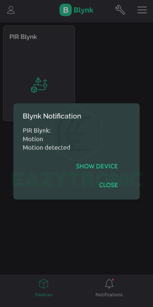
}Last is this function call that simply read the value from the PIR Sensor and according to the condition updates the value at the V1 address of the server. In the first line, we write a condition to check whether the output from the PIR sensor is HIGH or not. If it is HIGH, then the flow of the program will proceed inside the condition. Inside, we write the 1 or HIGH to the V1 address of our device widget at the server. Also, we log the event as a warning to the user as motion is detected. This will be indicated as a notification from the Blynk App regarding the suspected motion in front of the PIR Sensor. Make sure to use this feature carefully, as in the free version there are only 10 warnings allowed per device per day. For an increase in warning, you need to upgrade your plan.
On the other hand, if the input from the sensor is LOW, then the value updated from the server will be 0. No notification will be sent to the device in this condition, as the value doesn’t change.
With this, we have completed our tutorial on PIR Sensor with Blynk. I hope you like it, and if there’s any issue with the code, comment down below. I’ll rectify it ASAP.