
Hello friends, today we’ll start IR Sensor with Blynk App. In this series, we’ll see the interfacing of different sensors and operate them via Blynk App. This is the first article in this series, therefore we’ll start with some very basic sensors. We’ve previously made interfacing articles of IR Sensor with other development boards as well. Furthermore, the basic article dedicated purely to IR Sensor is also available, you can read it What is IR Sensor. In upcoming sections, we’ll explain the steps to control and read the values from NodeMCU Board to Blynk App. If you want to read interfacing with other development boards, that can be found below at the end. Now, without wasting any time, let’s start with today’s discussion.
IR Sensor and NodeMCU in Brief
IR Sensor
These are one of the most easy to use beginner-friendly sensor. These sensors can be easily interfaced with any development boards and can easily adapt to any logic level of the board. Moreover, the schematic for cloning the sensor is very easily and that be found here What is IR Sensor. This sensor comes in two version that are easily available in the market. LM393 & LM358 are the two IC that are use in making the circuit of IR Sensor. Overall, the difference in version of two version is mainly due to the IC used for operating them.
IR sensor work on the phenomena of the reflection of light mainly and several other phenomena that are mentioned in detail in their article. Although these sensors are quite easy to use, there are certain limitations for these sensors. First, this sensor cannot work on dark surfaces, as those surfaces tend to absorb all the infrared light. Moreover, an extremely bright environment like direct sunlight or direct fire flame is not a suitable environment for the usage of this sensor.
NodeMCU
NodeMCU is one of the most popular boards for IoT applications. This board is a small version of ESP32 boards, but their application and features don’t lack much behind. This board contains Tensilica Xtensa LX106 32-bit RISC Microprocessor that can run RTOS at a variable frequency rate of 80-160MHz. To differentiate this chip from others it is named ESP8266 or ESP12-E commonly. Despite this, you can program this using the Arduino IDE or Python Code. However, the chip is made for compact enclosures, as a result, it has limited flash storage and lacks certain features as compared to ESP32.
ESP8266 SoC is paired with 128 KB of SRAM which is quite sufficient for most of the projects along with 4 MB of Flash ROM Storage. It also comes with an 802.11 b/g/n Wi-Fi Transceiver, but doesn’t have Bluetooth support. In addition to this, NodeMCU has enough pins for attaching sensors also powers pins, but you can’t put much power load on it. As the components are mainly SMD, replacing them is a bit tiring and costly. On the other hand, it supports all types of communication that a board should. Hence, it is the most suitable board at a low cost for IoT devices and very easy for beginners to start with.
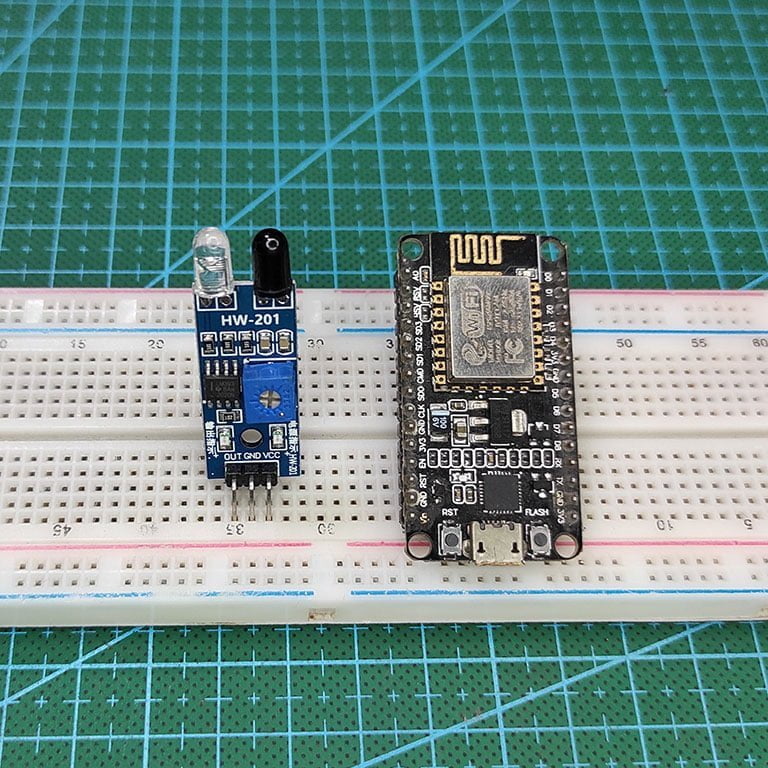
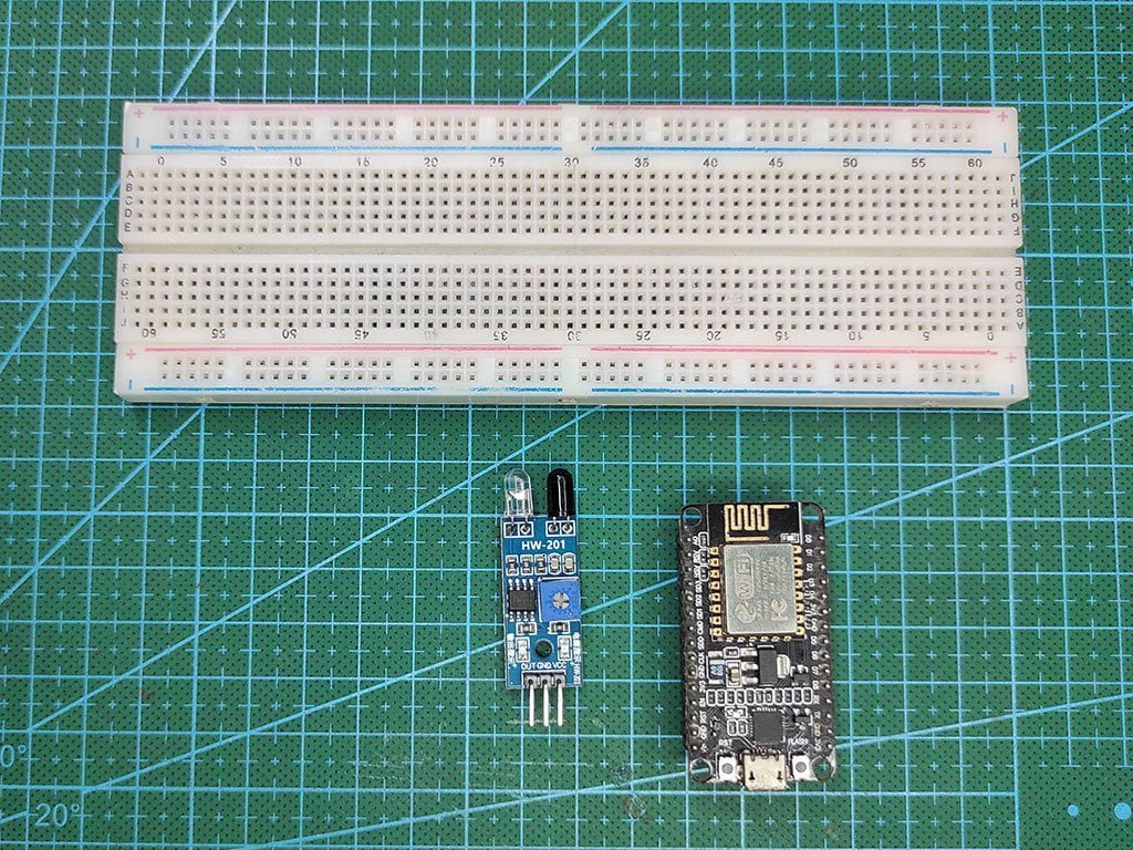
Material Required
Below are the components that are required for the demonstration of this interfacing. All the components are easily available on the local market or can be bough online at affordable prices.
- NodeMCU
- IR Sensor
- Jumper Wires
- Breadboard
- Blynk Interface on phone and desktop both
Fritzing Schematic
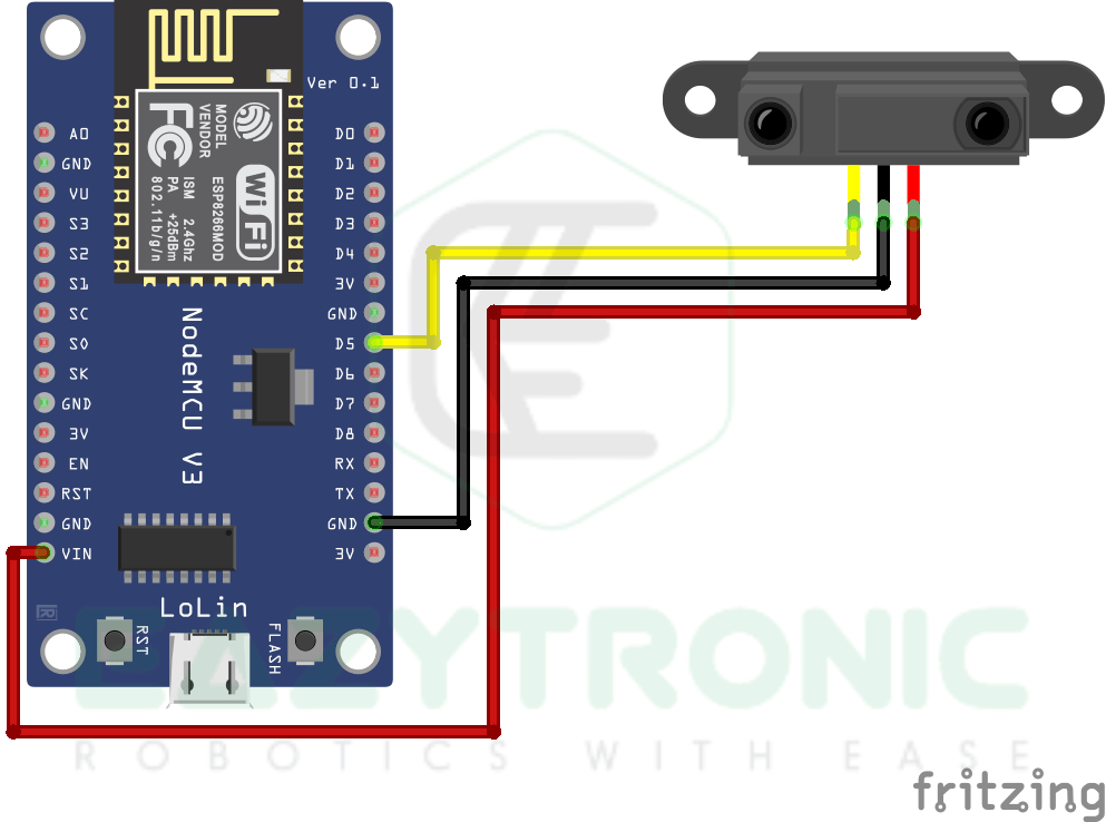
Wiring
| NodeMCU Pin | Sensor Pin |
|---|---|
| VIN | Vcc |
| GND | GND |
| D5/GPIO14 | VOUT |
Designing Blynk Interface
For designing the blynk interface, we’re going to start with everything new. However, if you are a previous reader and have made different devices and templates before. Hence, you just have to add the templates and device, therefore there might be some changes in options. So interpret the steps according to your conditions. Now we can proceed to the next step for this you have to visit blynk.cloud, make sure you are logged in, in both the web dashboard and mobile dashboard. Now we’ll separately design the web dashboard and mobile.
Web Dashboard
- First, go to blynk.cloud and log in with the ID and password. If you haven’t created one, then create one and log in with it. Also, make sure to log in with the same ID and password in the Blynk App.
- Once you have done this step, you’ll be taken to your dashboard, from here you’ll be controlling all the major things. Now we’ll start our main design.
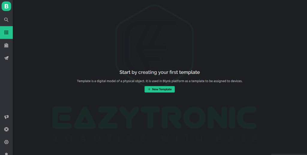
- Now check on the left menu from there select the icon just below the magnifying glass, this is the template tab where we’ll start creating the dashboard. Reference images are attached below.
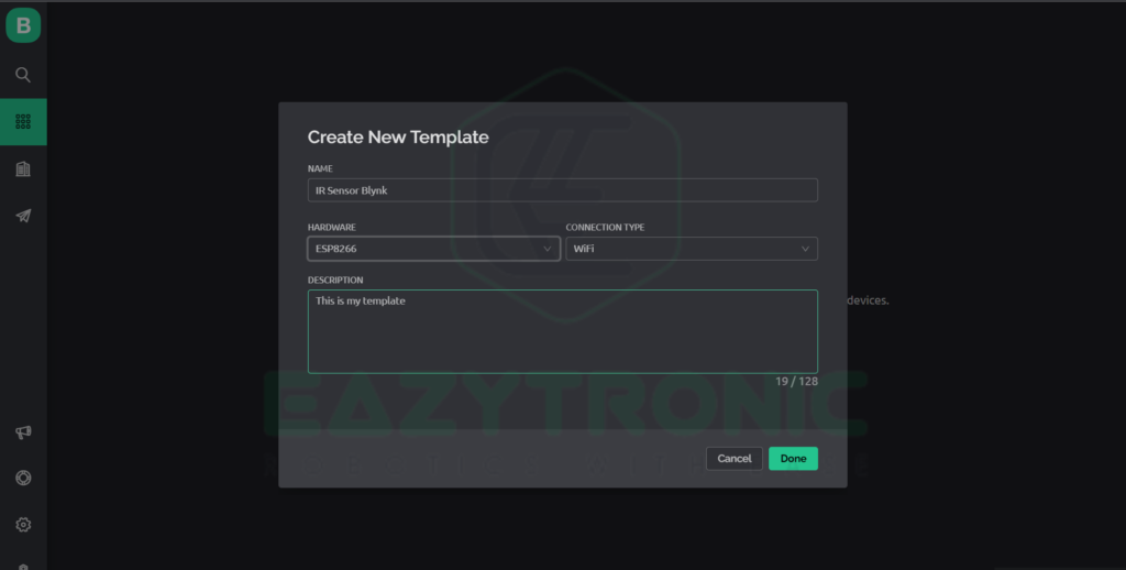
- Click on the +New Template button in the center of the screen. A dialog box will show up on your screen asking for some details about your template. Fill in all the details and click on Done.
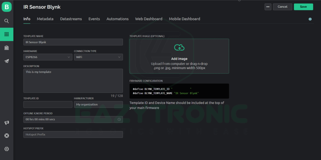
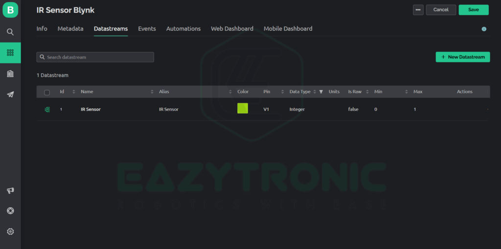
- This will take you to the template you just created that will look something like this. Now we’ll create other necessary things for controlling IR Sensor. Now switch to the Datastreams tab from the above menu.
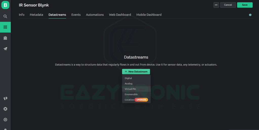
- Now click on +New Datastream Button in the center to create one. Once you click on it, a drop-down list of types of datastream will appear. From this select Virtual Pin.
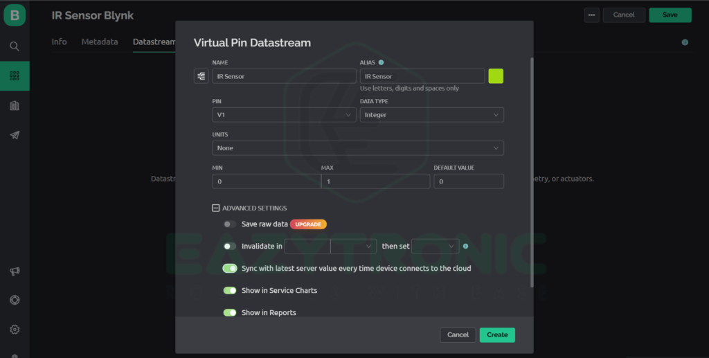
- Fill in all the details, and make sure not to change the crucial ones, as these can affect your project working or cause any errors. Below is the reference image for this purpose. Once done, click on create button.
Widgets design
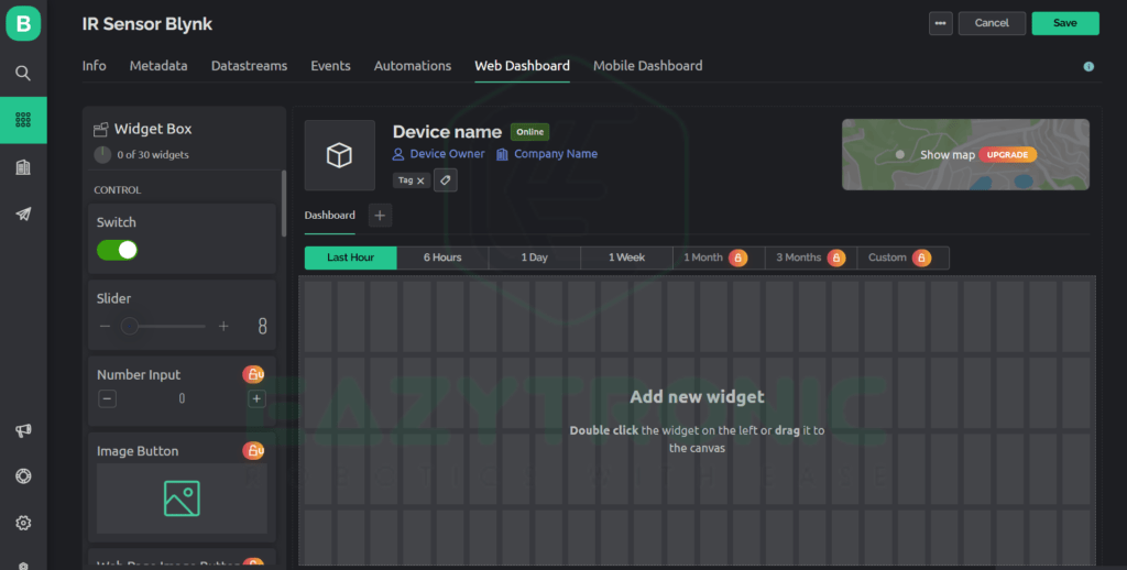
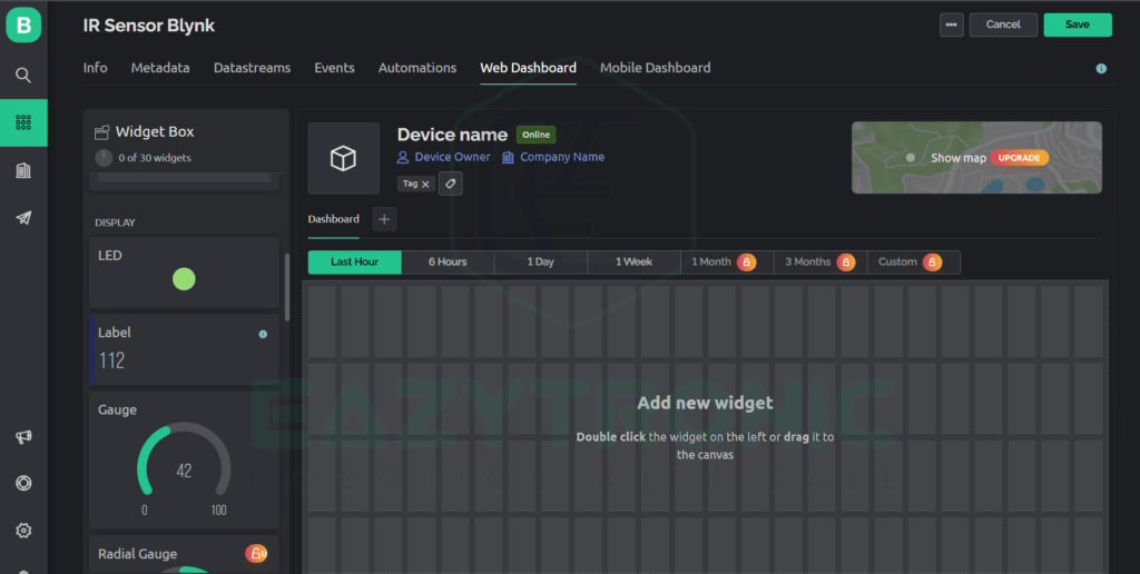
- After this switch to Web Dashboard, there will be a blank space where you can drag and drop widgets. For this, from the left menu of widgets drags the Label widget and put it in the blank space.
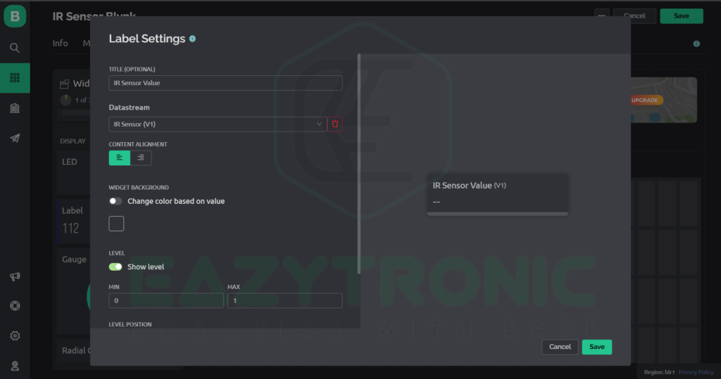
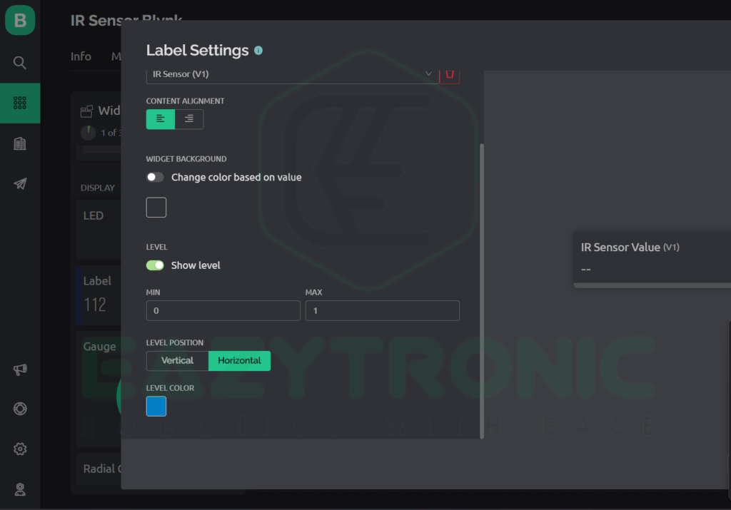
- Now, to change its settings, hover over the widget and select the gear icon. In the appeared dialog box, change the settings as shown in the below image. You can change the non-crucial information like the color and name.
- Once done, click on save in the dialog box and again on the top right of the screen. This will save your template, and now you are towards completion of your web dashboard design.
Device creation
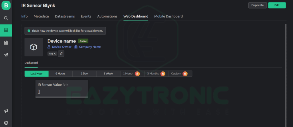
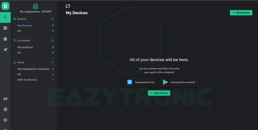
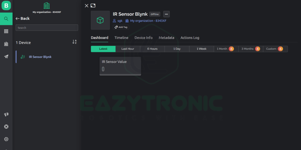
- Once you’re done, the complete template dashboard will look like the image below. Now we have to create the device, for this on the left menu select the magnifying glass icon.
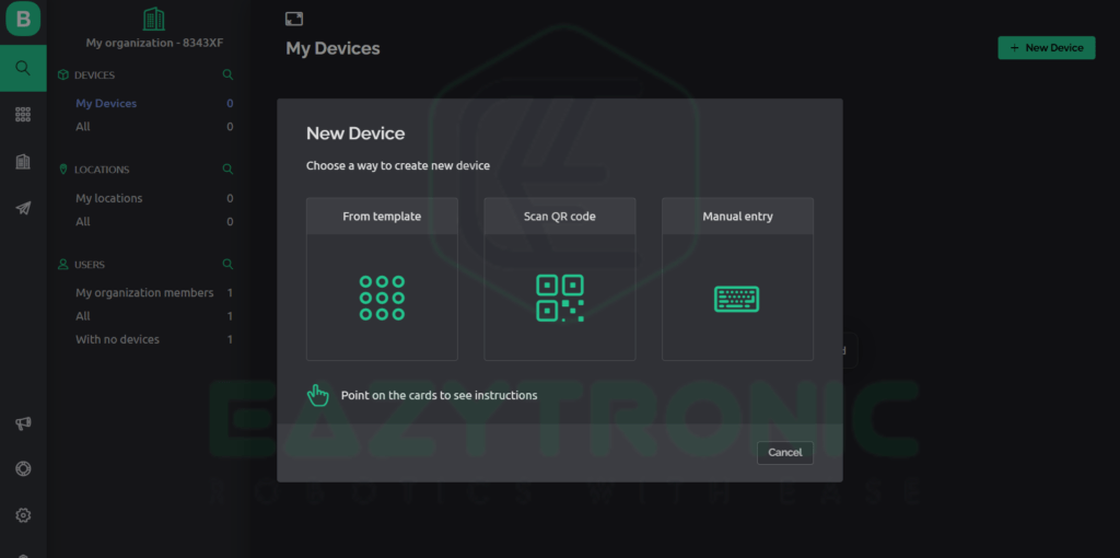
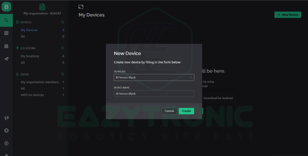
- There you need to create a device, click on +New Device, then click on From Template, this will let us create a device from the template we just created.
- Select the template and click on create, with this we’re done with the Web designing part Now we’ll switch over to Mobile Dashboard.
Mobile Dashboard
- As we have completed our Web Dashboard design, we can now proceed toward mobile dashboard design. This is more simple than web dashboard designing.
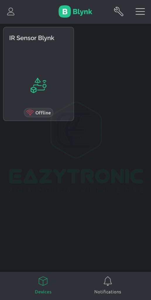
- First Download the App from your platform app store like PlayStore or Apple Appstore. Once downloaded, open the app and log in with the ID and Password you created.
- After you log in, just refresh the App, and you’ll see the device and template we created on the web dashboard appear on it. Now click on it to set it up for mobile.
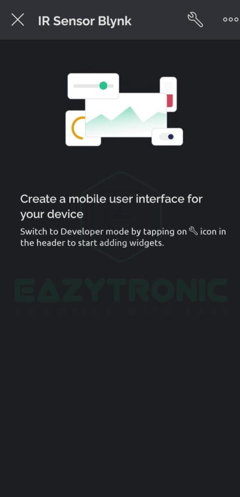
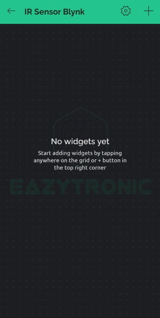
- Once you click, a blank screen as shown below will come in front of you. Here we need to add the widget to display and control the sensor values.
- For this, click on the wrench icon in the top right section of the mobile, and a blank screen where you can add widgets will appear. Here you can add a widget just like the web dashboard.
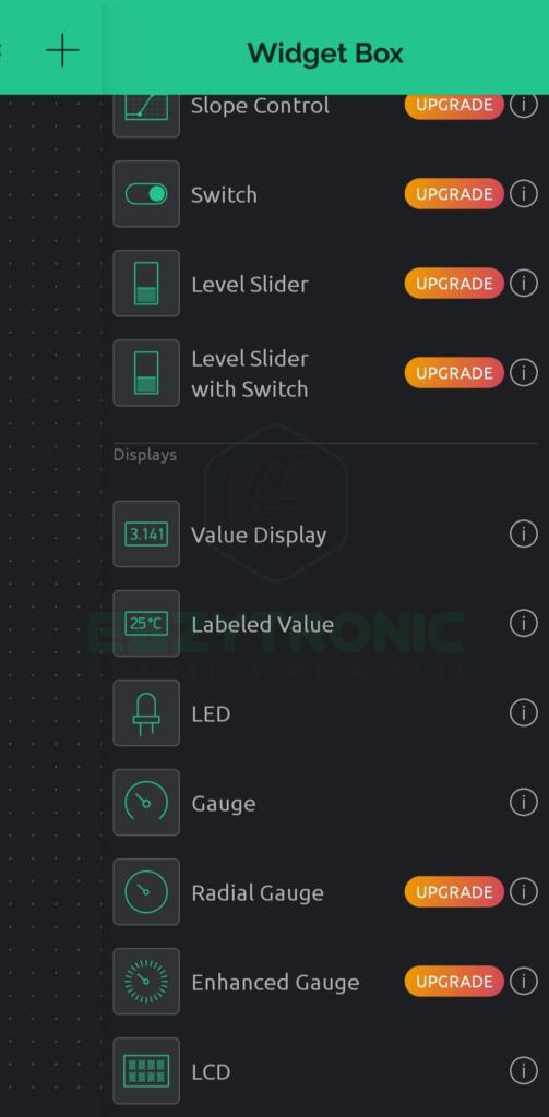
- Now click on the + icon in the top right section of the window. Upon clicking, a slide menu from the left will appear containing a list of all the widgets. Here, you can see the widgets according to your plan of Blynk Server. I’m using free version, so using only free widgets.
- Now select the Labeled Value widget from the list, Just click on it and it’ll appear in the blank space. Now drag it to adjust its position and size.
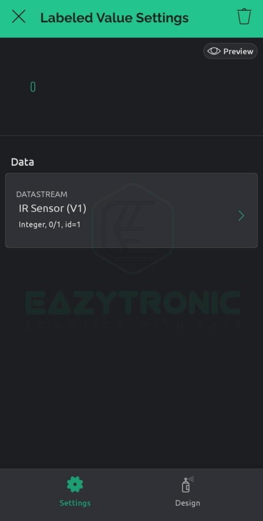
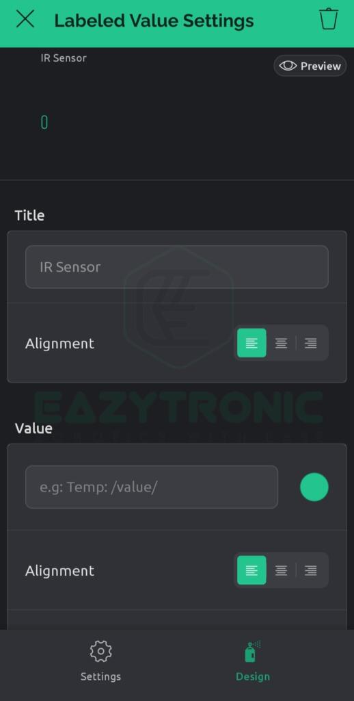
- After this, click on the widget to change its settings regarding datastream and others. In the Data, section select the datastream we just created, and the rest are user-choice settings like design and name.
- For reference and more clear instructions, below are the attached images of all the steps. Make sure to look at them if needed help. With this, we have done setting up the mobile dashboard.
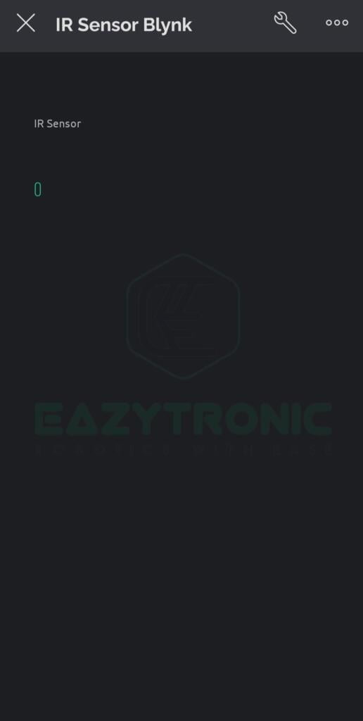
- Now just return to the main screen inside the device, here we can now see the widget with the name and sample value 0. Now we’re ready to program our microcontroller for code.

Programming NodeMCU
Now as we have done the Blynk part, we can now program the board. Before we proceed further, make sure that you have updated all the board definitions and libraries. Also, make sure to install all the essential libraries that I explained in NodeMCU with the Blynk article. Once done with all these steps now we can finally program our board. Below is the complete code, followed by its explanation.
Code
#define BLYNK_TEMPLATE_ID "your template id"
#define BLYNK_DEVICE_NAME "your device name"
#define BLYNK_AUTH_TOKEN "your  auth token"

#define BLYNK_PRINT Serial

#include <ESP8266WiFi.h>
#include <BlynkSimpleEsp8266.h>

char auth[] = BLYNK_AUTH_TOKEN;

// Your WiFi credentials.
// Set password to "" for open networks.
char ssid[] = "Wi-Fi SSID";
char pass[] = "Wi-Fi Password";

int ir = 14;
int val;
BlynkTimer timer;
void myTimerEvent(){
  Blynk.virtualWrite(V1,val);
}

void setup()
{
  Serial.begin(9600);
  Blynk.begin(auth, ssid, pass);
  pinMode(ir, INPUT);
  timer.setInterval(100L,myTimerEvent);
}

void loop()
{
  val=digitalRead(ir);
  Serial.println(val);
  Blynk.run();
  timer.run();
}
Save this code with any name, but for better understanding, make sure to save them with some meaningful name. Also, the pins used are for experiment purposes, you can change them as you want but make sure to do everything correctly.
Explanation
Here comes the most important part of any article, an explanation of the code. We’ll be explaining code in the small segment so that it can be easier for you to modify it according to your need. So let’s start with this.
#define BLYNK_TEMPLATE_ID "your template id"
#define BLYNK_DEVICE_NAME "your device name"
#define BLYNK_AUTH_TOKEN "your  auth token"
First, in the code, we define some very critical lines of code. These lines are Auth Token, Device ID & Template ID, these all are essential to differentiate from your several projects. Moreover, these 3 pieces of information are very crucial as without these you won’t be able to make communication between NodeMCU and Blynk Server. Also, if someone else had a grasp of these 3 things, then they can easily manipulate your project. NOTE: Keep these 3 information private, if you disclose it anyone can control your project.
#define BLYNK_PRINT Serial

#include <ESP8266WiFi.h>
#include <BlynkSimpleEsp8266.h>
Next, we include some libraries that are required for the program to compile and work. In addition to this, these libraries can differ from board to board, so make sure to verify the correct libraries for your board. For more information, read the corresponding board article with Blynk App.
char auth[] = BLYNK_AUTH_TOKEN;

// Your WiFi credentials.
// Set password to "" for open networks.
char ssid[] = "Wi-Fi SSID";
char pass[] = "Wi-Fi Password";

int ir = 14;
int val;
BlynkTimer timer;
Next, we initialize some variables to store some information that we’ll be using further in the program. These variables can differ according to the user’s needs, also naming them differently will also not affect anything. However, in the last 3 lines, we have defined some important things. First, we define the pin on which we’ll be connecting our IR Sensor to the board. Next, we define a variable to store the value coming from that IR Sensor. Finally, we define a timer object that we’ll be using further.
void setup()
void setup()
{
  Serial.begin(9600);
  Blynk.begin(auth, ssid, pass);
  pinMode(ir, INPUT);
  timer.setInterval(100L,myTimerEvent);
}
This section contains the code that needs to be done only once, also some important tasks need to be done like beginning the communication. First, we begin the serial communication at 9600 Baudrate, you can change this if you want as this will not affect any functioning of the code. After this, we begin the communication of the NodeMCU board with the server using the AUTH TOKEN defined above in the code. Along with this, Wi-Fi, SSID, and Password will be used to establish an internet connection. Further, we define the mode of the pin on which we connect the IR Sensor. Since we’re going to grab values from the sensor, hence we have initialized it as an INPUT pin.
In the last line, we set the interval between sending two consecutive values to the Blynk Server. As there is a limit of a maximum of 10 values in one second. Therefore, we can either set the interval manually according to our need.
void loop()
void loop()
{
  val=digitalRead(ir);
  //Serial.println(val);
  Blynk.run();
  timer.run();
}
This contains the main code of the project, in the above-mentioned code some lines correspond to other function calls as a part of Blynk code. Overall, we can say that for every Blynk operation, there might be a different function that needs to be called at that instant. In the first line, we first read the value of the IR Sensor and store it in a variable called value. The next line is to check the value coming from the IR Sensor, as it may vary according to your model. Next, we run a very common command in Blynk codes, i.e., Blynk.run().
This line communicates with the server and refreshes the status of values transmitting and receiving from both the Board and Server. Finally, we call timer.run() command to update the value on the server to display the status of the IR Sensor. We can also modify this code to create a pop-up notification on the mobile device, but that will be some other article, and I’ll link it below when updated.
Timer Function
void myTimerEvent(){
  Blynk.virtualWrite(V1,val);
}
This function is important to update the values on the server. In this section, we’ll only include code that updates the value of the corresponding virtual pin on the server. Here, as I have used virtual pin 1 for sending values of the display so v1 and the value coming from IR Sensor are directly sent to the display on the app and server.
With this, we have completed our demonstration of the IR Sensor with the Blynk App. I hope you like it, if you have any issue with any part, comment down below I’ll help you there.