
Hey folks, Today we’re starting a new section of NodeMCU with Blynk App. This series will contain all the IoT tutorials and projects that can be used. Blynk App is one of the most common IoT platforms which has enabled beginners to practice their projects. There was a previous version of the Blynk app that doesn’t work anymore, or can say has been upgraded to the new one. As the interface is new and needs new ways to be set up, in this article I’ll tell you how to set up the new Blynk IOT App with NodeMCU. So without wasting any time, let’s begin.
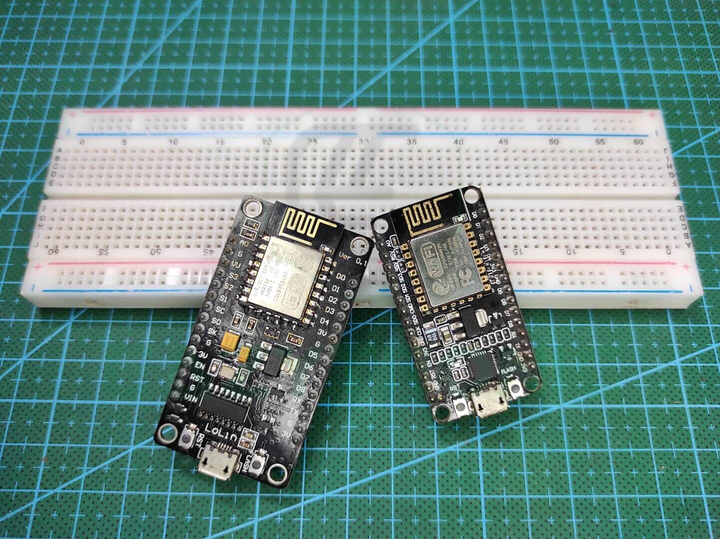
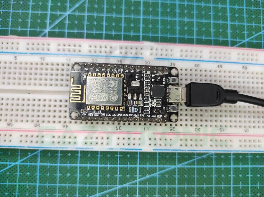
NodeMCU ESP8266
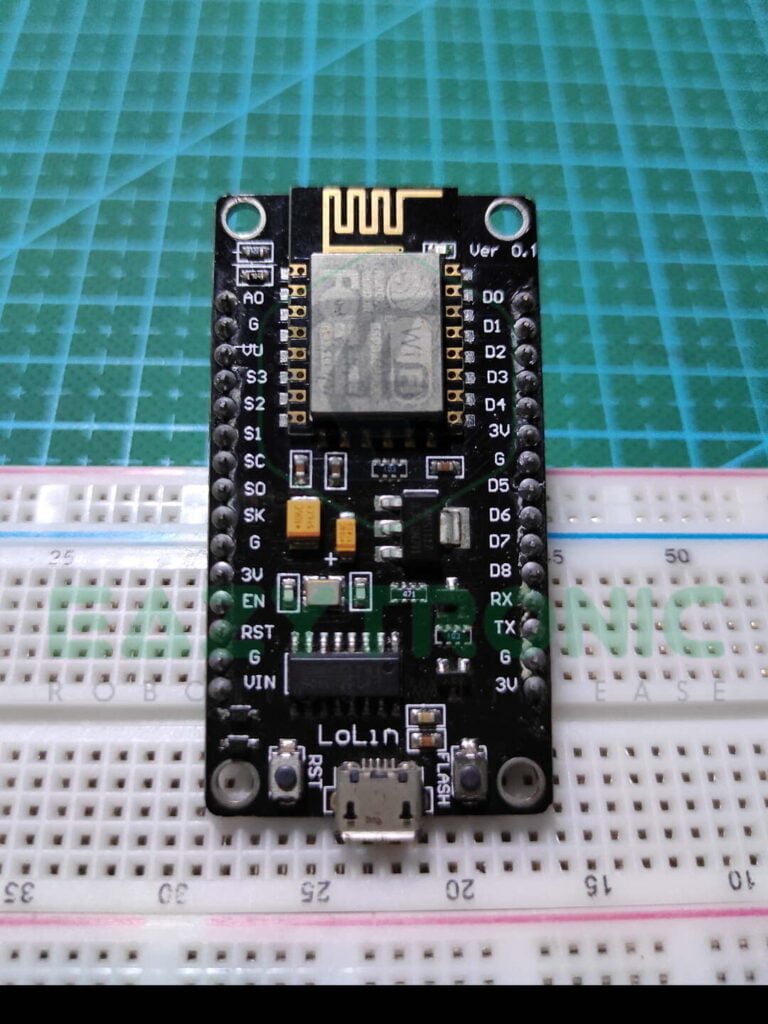
This is the main component of this tutorial, you can replace this with any other ESP Board. But for now, let’s use the simple one ESP8266 aka NodeMCU. NodeMCU is a very powerful development board for many projects that can do multiple tasks with such a small form factor. This board comes encloses Tensilica Xtensa LX106 32-bit RISC Microprocessor which can perform tasks like butter. It works on RTOS and can be operated at a frequency range of 80MHz-160MHz. This frequency can be adjusted, and this whole comes in a very small chip, namely ESP-12E.
It is paired with 128 KB of SRAM that is divided into 2 parts 32 KB & 80 KB for maintaining and starting the RTOS for normal working. You can add SPI flash to the ESP8266SoC, however, it comes with a 4 MB of SI flash which is more than enough for many projects. These specifications are more than enough, but it also supports OTA update, for which SPIFFS memory is allotted separately. Moreover, the main feature of NodeMCU IoT, it comes with an 802.11 b/g/n Wi-Fi Transceiver. However, it only supports Wi-Fi capabilities, Bluetooth feature is available in different series of Boards, but this is more than enough for a beginner.
It has many GPIO Pins and these are enough for many operations, but the only drawback is that the pin tolerance is only 3.3V. Also, the number of power pins available for connecting the peripherals and sensors is very less, this needs to be improved. On the other hand, there is an LDO that enables powering the board with a power supply and reduces it to 3.3V for usage. Moreover, like any other microcontroller, it has a USB to Serial converter IC CP2102 or CH340G in clones, but overall they work like charm.
BLYNK App
Blynk IoT App, this app is the best open-source IoT application. This is widely popular as it is very easy to use and available for free. There was a previous version of this App that was also very popular, but with time it got upgraded with BLYNK IoT. Today in this article I’ll tell you all the steps to set up this new version of the BLYNK App. It’ll be covered in several steps that are explained in detail below.
Goto BLYNK.IO
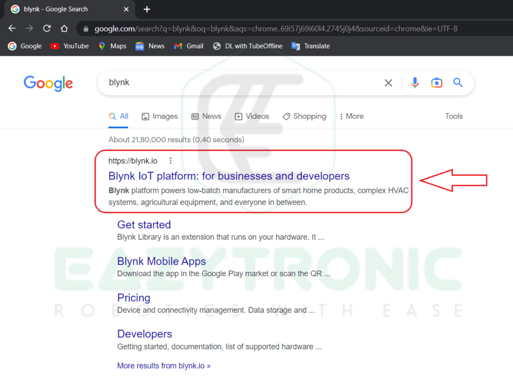
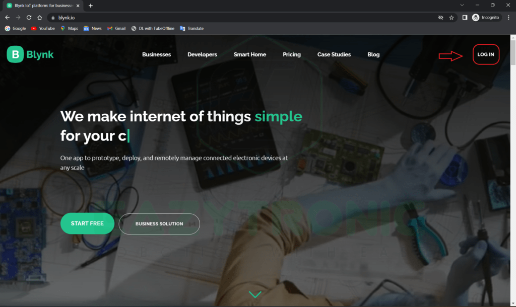
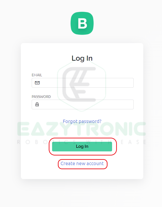
As this is a new version, therefore surely there is some twist in setting it up. For setting up the current version first you have to go to their official website i.e., blynk.io. After the webpage opens, you can scroll through it for more information, but for right into the task. Click on the login button on the top right, Log In with the ID, or create one if you don’t have one. After creating and logging in, you’ll come through a console like in the below image.
Creating New Template
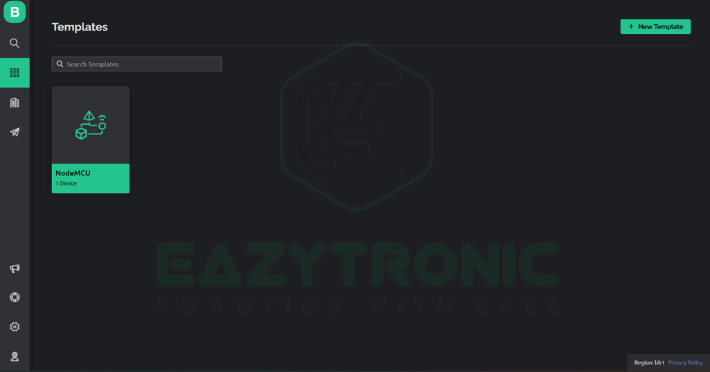
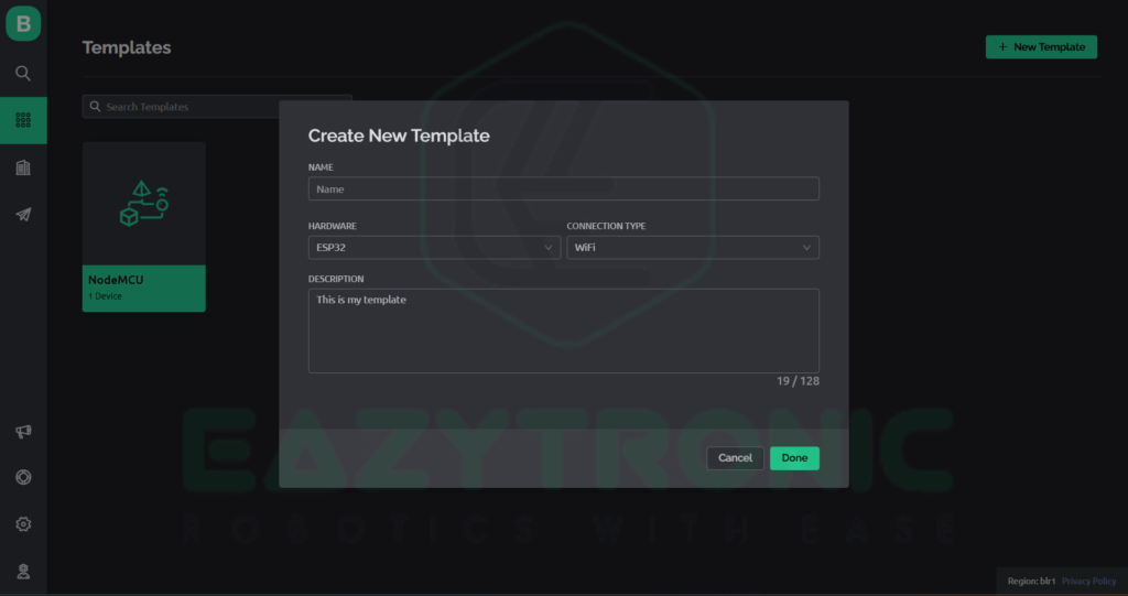
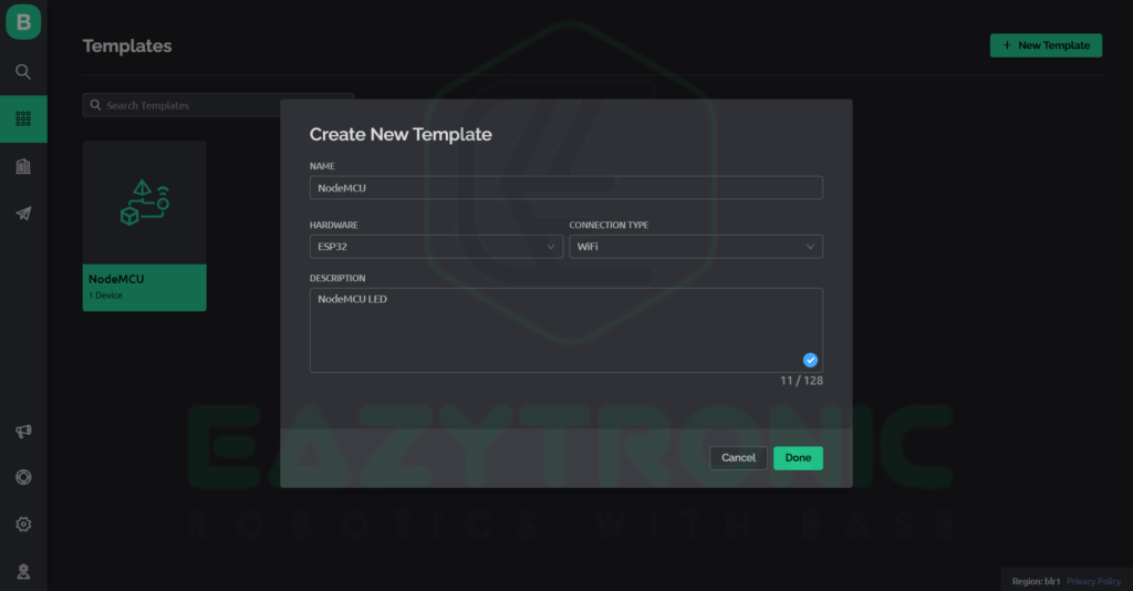
As I have already created a device for testing, so disregard this, but I’ll show you how to create one. First, on the left side, there is a menu to select the second icon there. On this screen, you need to create a template to control the device. On the top right there is the New Template button, click on it and a screen pops up right in front of you. Fill in the name for your template and the board you are going to use, and also give a good description for it. If you have more than one template with the same name as I do.
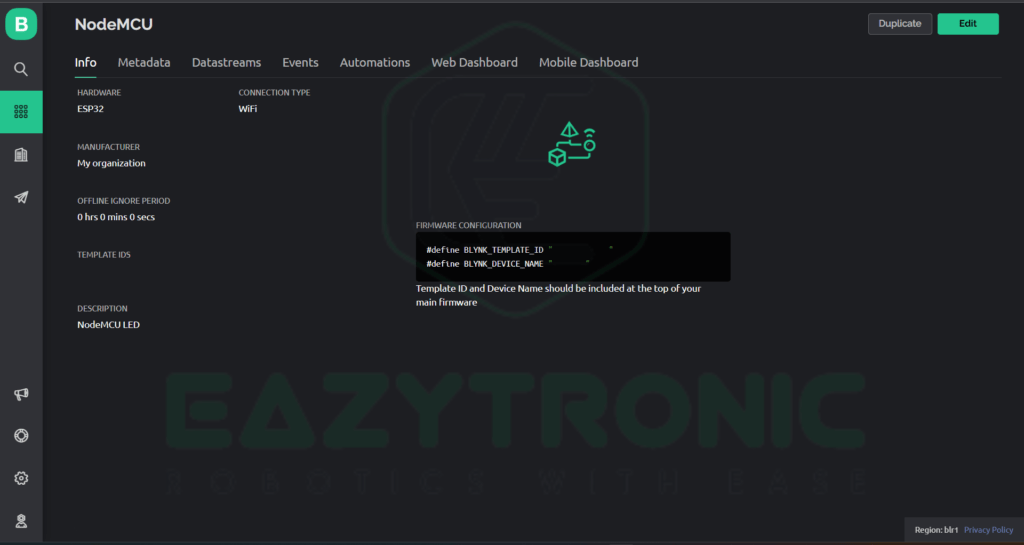
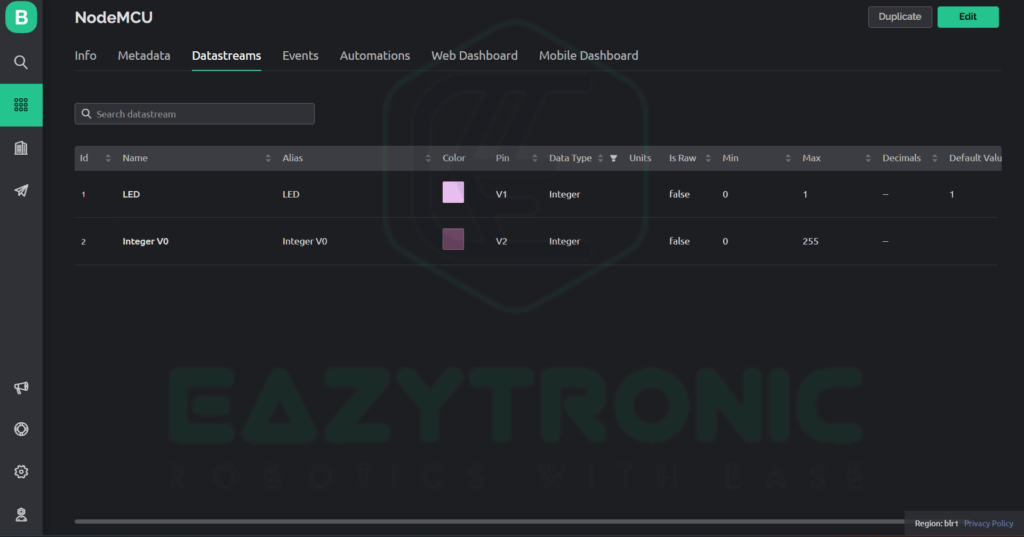
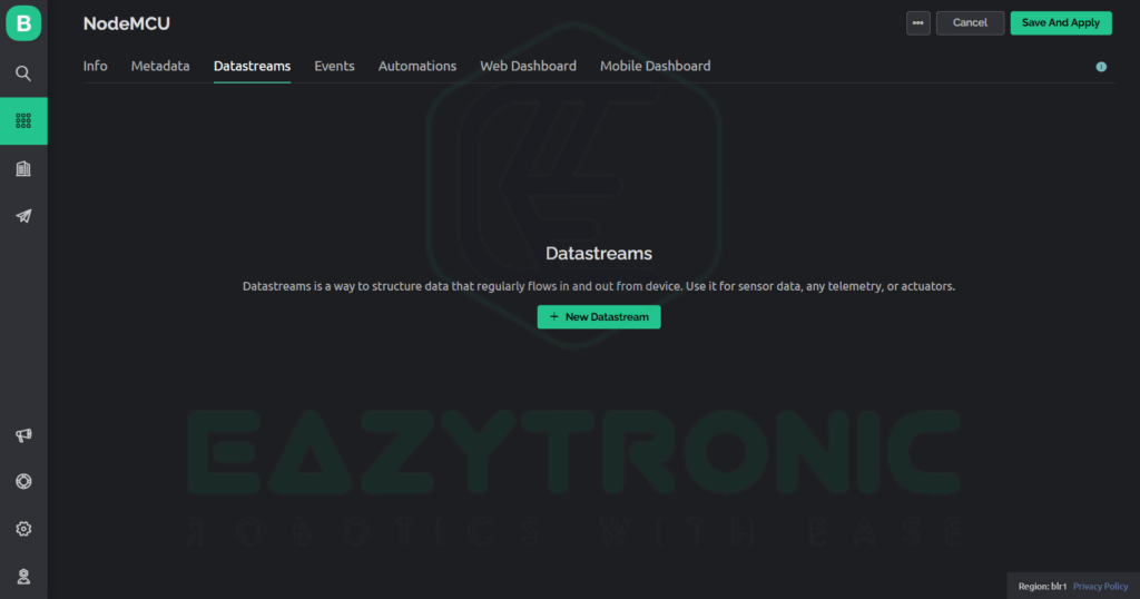
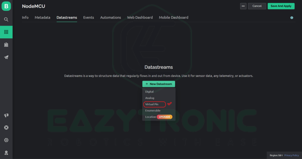
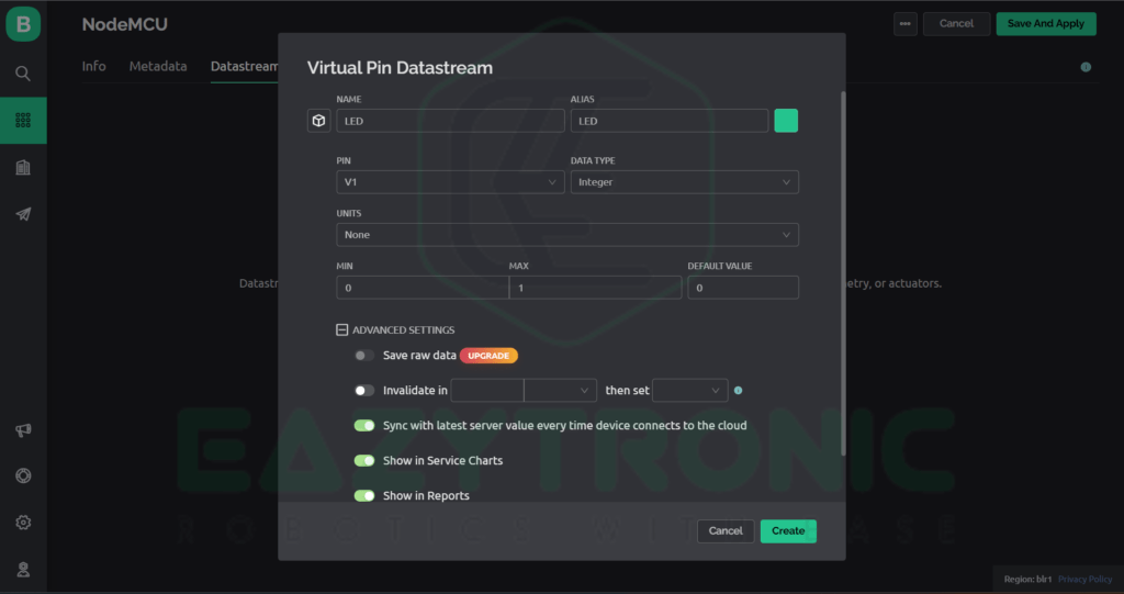
Once created, click on the template you recently created to open it. Never share the information on the Info tab, as it contains critical information regarding your template. Next, switch to the Datastreams tab and click on the New Datastream button to create one. There you’ll be asked to create a certain type of Datastream, I’ll choose Virtual pin here. The advantage of selecting a virtual pin here is that you can change its function inside the code. Otherwise, if you have selected digital or analog, you have to change it via the web dashboard. Once selected, a screen will appear where you have to fill in all the necessary values. Give a name to the datastream and select a virtual pin, for now, let’s select V1 and other values like max min value, etc.
Creating New Device
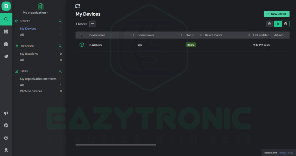
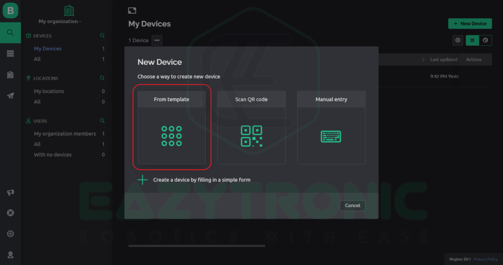
Now we have to create a device that will be used for implementation. I have used NodeMCU for this purpose as mentioned in the template. For this click on the search icon on the left side menu there you’ll see My devices. Click on + New Device, in my case it is on the top right, but it may be different in your case. As soon as you click a screen will pop up, there you have to select how you want to create your device. Select Template and continue, after this, you’ll be asked for the template you want to use. Select the one you recently created and click create, with this you are done with the web dashboard part till now. In a later part, we’ll see how to create widgets in both phone and web dashboards.
Creating widgets
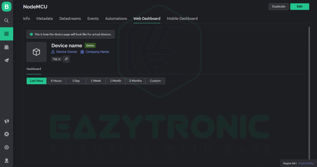
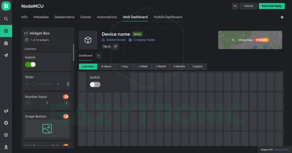
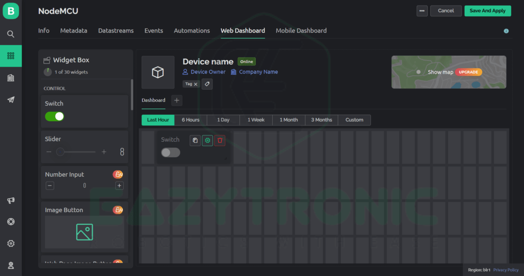
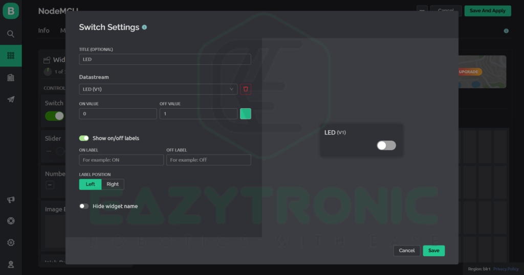
First, we’ll see how to create widgets on the web dashboard, for this go back to the template menu and open the template we’ve just created. Now click on the Web Dashboard tab, and an interface like this will appear. Click on the Edit button on the top right, suddenly the blank area will change into some blocks and on the left several widgets will appear. Select a Switch widget and drag it into the block area, now click on the gear icon on the widget to edit it. Now in the dialog box, change the switch title that suits your project and select the datastream you just created. Below is the image for reference. Change the ON & OFF value if you are using the onboard LED of NodeMCU like I’m doing. Click on Save and Apply and the widget is saved and ready to use.
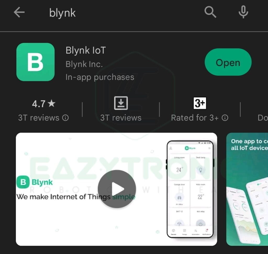
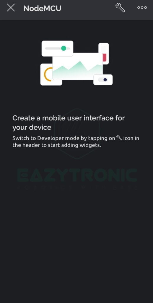
To control this via mobile, you first have to download the BLYNK IoT App from PlayStore or App store. Next, open the app and log in with the ID and password you used to create on the Blynk website. Upon opening, you just have to refresh the App and the device with the template will automatically appear on the main screen. Next, you just have to make the mobile dashboard. For this, click on the device that appeared on the main screen. Once it opens up, click on the wrench icon in the top right of the screen. A new screen will appear, here you can add widgets just like the web dashboard to control your project.
Adding Controls
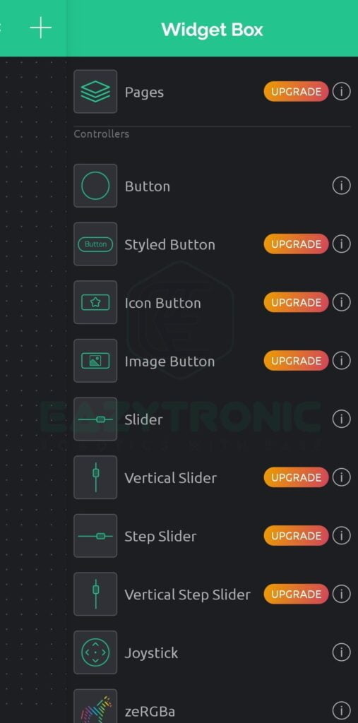
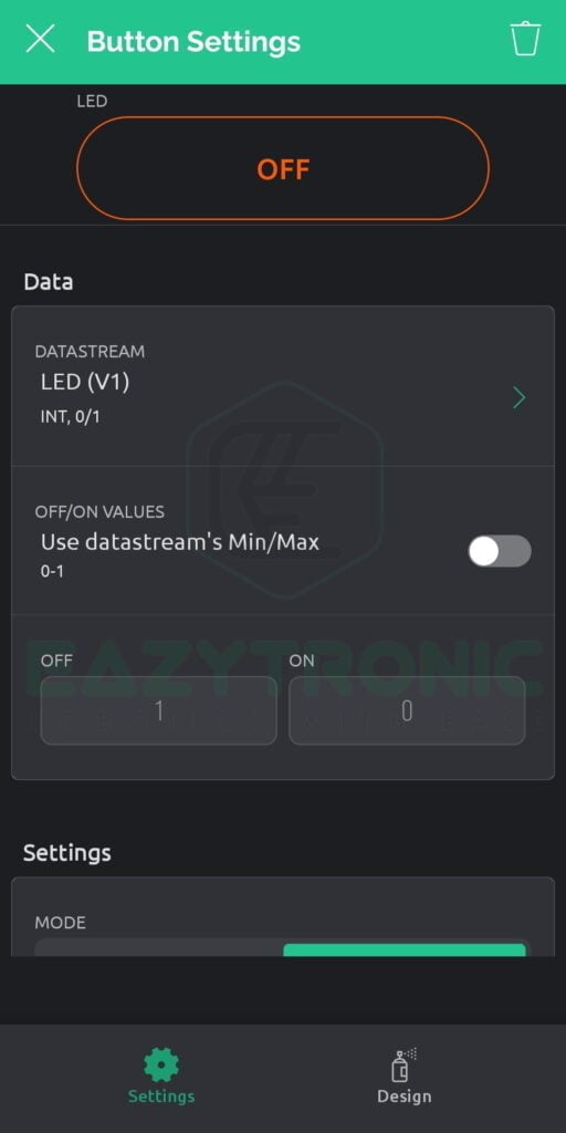
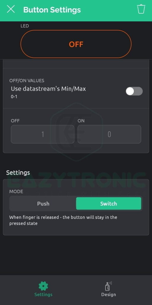
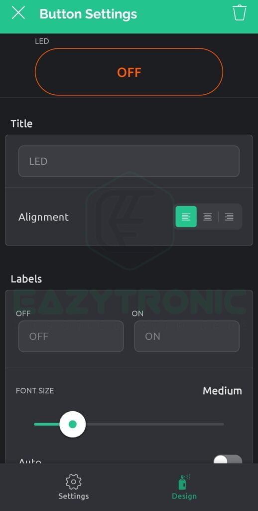
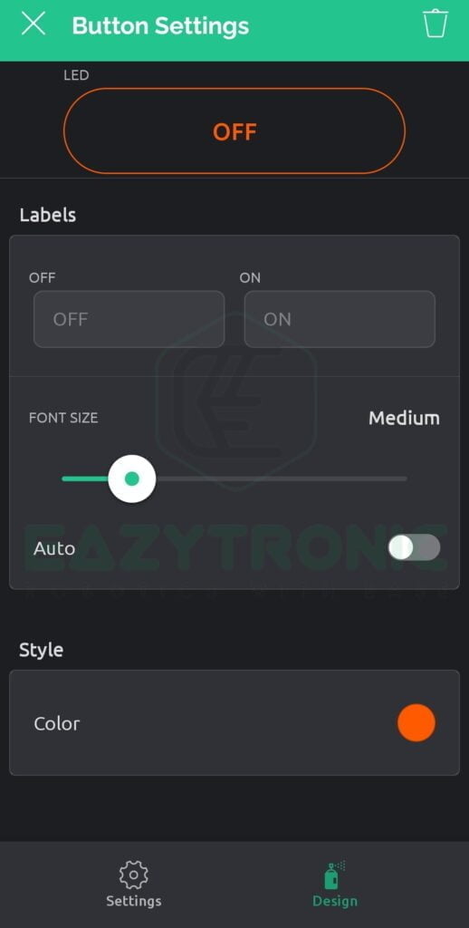
Next, click on the + symbol, in the top right, and a right-side menu of widgets will appear. From here, you add several widgets by simply dragging and dropping, or just clicking on them to add them. To adjust the size and placement of it, simply long press on it, and it’ll move and can be resized. To choose the datastream tap on the button and button settings will appear. Further, in the datastream section, click and select the datastream you want to use or just created and play with other settings for more understanding. Below is the image for reference.
Programming NodeMCU
Now comes the interesting part of programming the NodeMCU board with Arduino IDE. You can use the code from the previous version of the app, but I cannot guarantee that the code will work for all the projects. Besides this, I’ll also provide new code and widgets designing steps with every upcoming article. So don’t worry if any beginners are reading this post, I’ll cover stuff for them in utmost detail. For this, make sure you have downloaded the latest version of Arduino IDE and updated its libraries and board definitions. The steps to set up a NodeMCU are explained in one of my previous articles, Getting Started with NodeMCU. Along with these, several other things need to be done to program the board.
Installing Library
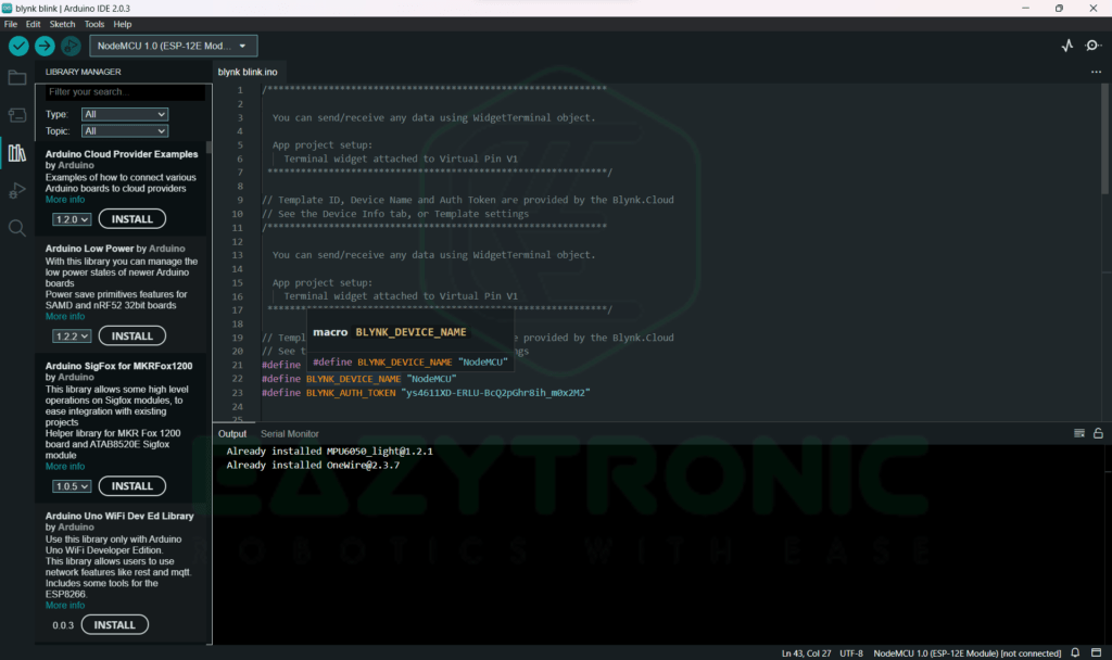
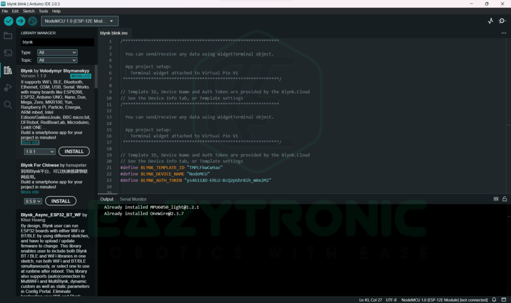
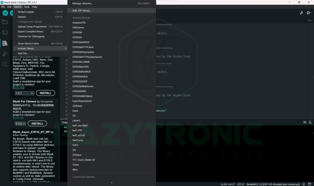
To program the board, we need to install the BLYNK Library, we can do this in two ways. First, we can use the library manager of the Arduino IDE. Secondly, we can download the zip file from the official website that enables you to use NodeMCU with BLYNK App. To install the library from the library manager, select the library manager from the left side menu. Next, search for “Blynk” in the search box and install the first one. After completing the installation, restart the Arduino IDE if the library and examples didn’t appear.
On the other hand, install from the zip file. Visit the official documentation website and search for the BLYNK library in the search bar. This will lead you to the GitHub Repository, from here you can download the latest library. Then install the library using the menu bar from above. Sketch > Include Library > Add .ZIP library.
Code
Once you have completed all the steps mentioned above, you can start writing code for your board. Many of you might be experienced people who have previous version code. Furthermore, if you want to combine or update the combined code for a project from the previous version then, you can skip this part. Beginners need to read this as I’ll explain how you can get any code syntax very easily which works just correctly. If you are a beginner and need correct code without much going here and there, then simply bookmark this website. There are many code examples available on this website and most of them work just fluently.
However, you can also use the previous code and check whether they work now also or are just a time waste. I also so, such thing as writing new code from scratch is very time-consuming and mentally tormenting. Below is the code which works just fine with both models original and clone. I have tested this on both versions and works just fine.
/*************************************************************

  You can send/receive any data using WidgetTerminal object.

  App project setup:
    Terminal widget attached to Virtual Pin V1
 *************************************************************/

// Template ID, Device Name and Auth Token are provided by the Blynk.Cloud
// See the Device Info tab, or Template settings
#define BLYNK_TEMPLATE_ID "template code"
#define BLYNK_DEVICE_NAME "device name"
#define BLYNK_AUTH_TOKEN "auth token"


// Comment this out to disable prints and save space
#define BLYNK_PRINT Serial


#include <ESP8266WiFi.h>
#include <BlynkSimpleEsp8266.h>

char auth[] = BLYNK_AUTH_TOKEN;

// Your WiFi credentials.
// Set password to "" for open networks.
char ssid[] = "wifi ssid";
char pass[] = "password";
BLYNK_WRITE(V1)
{
  int pinValue = param.asInt(); // assigning incoming value from pin V1 to a variable
  //Serial.println(pinValue);   // testing line for loop
  //Serial.println("enter v1"); //    ''    ''   ''  ''
  digitalWrite(2, pinValue);
  //delay(1000);

  // process received value
}
void setup()
{
  // Debug console
  Serial.begin(9600);

  Blynk.begin(auth, ssid, pass);
  pinMode(2, OUTPUT);     // led pin , Using built-in led @ D2
  // You can also specify server:
  //Blynk.begin(auth, ssid, pass, "blynk.cloud", 80);
  //Blynk.begin(auth, ssid, pass, IPAddress(192,168,1,100), 8080);
}

void loop()
{
  Blynk.run();
}
Explanation
Now comes the explanation part, this is the most important part for beginners, as it helps them to understand the simple code. Let’s start from the beginning, below are code snippets broken down into small sections to make the explanation easier.
#define BLYNK_TEMPLATE_ID "template code"
#define BLYNK_DEVICE_NAME "device name"
#define BLYNK_AUTH_TOKEN "auth token"
First, we start with these 3 lines, these 3 lines are the most important. In other words, without this line, the whole IoT functionality will not work. However, these 3 lines can be copied from the dashboard either on the mobile dashboard or the web dashboard. If you are using only a web dashboard with simple code, then only auth token will be enough. On the other hand, if you are using Edgent code, then you’ll need and template_id & device_name. I have tried the Edgent code also, but there is a different application for that type of code. However, for simple projects, you can use simple codes like the one I’m giving to you.
#define BLYNK_PRINT Serial


#include <ESP8266WiFi.h>
#include <BlynkSimpleEsp8266.h>

char auth[] = BLYNK_AUTH_TOKEN;

// Your WiFi credentials.
// Set password to "" for open networks.
char ssid[] = "wifi ssid";
char pass[] = "password";
Next, we include some libraries and initialize some important items. In this part we first initialize the serial port, in the BLYNK code we have to define the BLYNK serials differently from the conventional one. Further, we include two libraries that are required for every blynk code for proper functioning. Next, we define our Wi-Fi details and auth token so that we can use them further in the code.
void setup()
This is the setup section of any code in Arduino IDE, that contains statements and operations that need to run once. Similarly, here also, this section contains code that needs on-time initialization. Below are the lines of code which exist in this section, these are explained below just after the code snippet.
Serial.begin(9600);
Blynk.begin(auth, ssid, pass);
pinMode(2, OUTPUT); // led pin , Using built-in led @ D2
// You can also specify server:
//Blynk.begin(auth, ssid, pass, "blynk.cloud", 80);
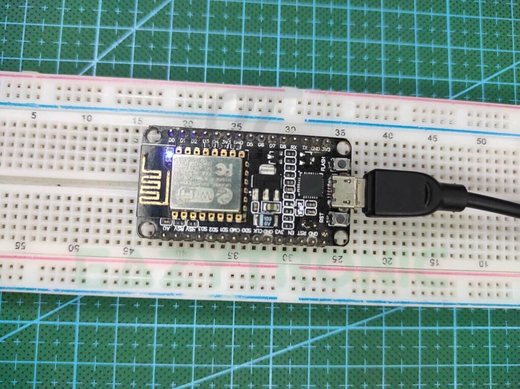
//Blynk.begin(auth, ssid, pass, IPAddress(192,168,1,100), 8080);First, we begin the Serial communication or console that the Blynk server uses to print necessary and user-required information. You’ll notice a fixed output every time the code restart. This output gives various information to the user like the cloud address, connection status, and others. Next, we begin the connection with the server using blynk.begin() function. Further, we define the pin to which the LED is attached, you can change it according to your choice. The next two lines are used for connecting different servers or if you have created your server at a different port address.
void loop()
This loop contains only a single line for now, as we are using the blink-led sketch. For more complex code and projects, It’ll contain different other subsections which control a different part of your project. This will be demonstrated in future upcoming articles.
Virtual pin loop()
This section or loop is for the virtual pin we have used in place of the digital or analog pin while creating the template. If you have used an analog or digital pin instead of a virtual pin, then this section will not come in the code. This is helpful in cases where you are experimenting and changing pins assigned to different sensors. Using this method, you can change them using the code without worrying about changing them actually in the template online.
BLYNK_WRITE(V1)
{
  int pinValue = param.asInt(); // assigning incoming value from pin V1 to a variable
  //Serial.println(pinValue);   // testing line for loop
  //Serial.println("enter v1"); //    ''    ''   ''  ''
  digitalWrite(2, pinValue);
  //delay(1000);

  // process received value
}
Here you have to make the different functional calls for different virtual pins, if I have used a virtual pin v1 address then I’ll make one for that pin. Similarly, it works for other pins, keep in mind that you have to give a separate function call for every virtual pin you created in the template. In the function call, you have to write the code that needs to be done on the input on that digital address. But before that, you have to store the value that is available currently at that address. To do this you have to enter the first line as such, but the type of variable will change according to the input it is receiving, so do regard this. The rest of the code is the same as the blink-led sketch from the Getting started with NodeMCU Article.
With this we’re done with today’s tutorial, I hope you’ll like it and find it interesting. If you have any issues in performing or doing as stated in the article then comment down below, and I’ll solve them ASAP.