
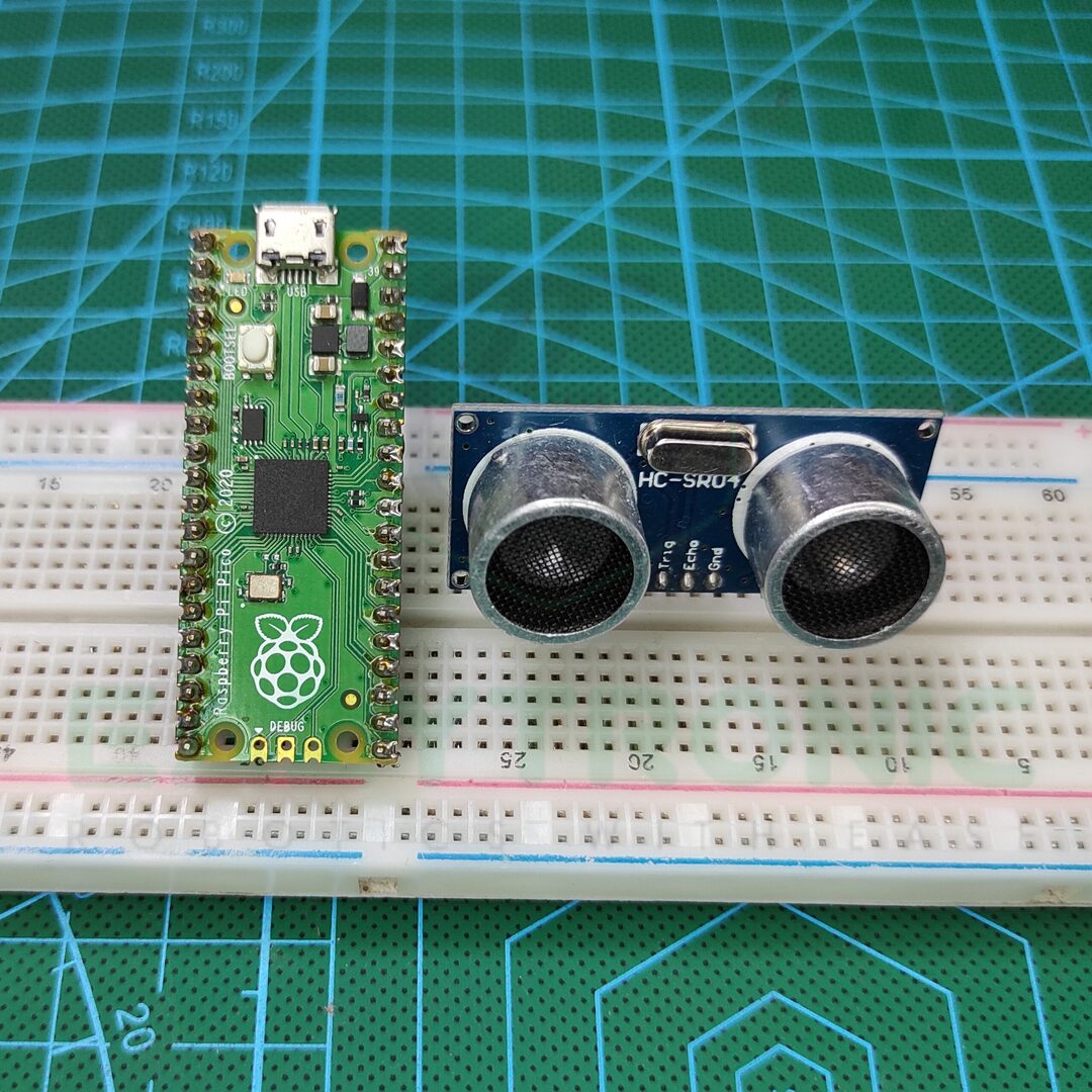
Hello Folks, we’re back with another interesting topic, Raspberry Pi PICO with HC-SR04. Ultrasonic Sensors are one of the basic sensors that a beginner can start with. In addition to this, it is easily available also easy to hook up with almost any microcontroller. These sensors are common for measuring distance in a small range and also make fascinating projects from it. In a previous article, we have explained this HC-SR04, Ultrasonic Sensor in detail, therefore for more information head over to that page. So, without wasting any time, let’s start today’s discussion!!
HC-SR04 Ultrasonic Sensor
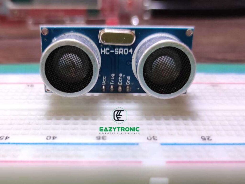
Ultrasonic Sensor, is one of the most used sensors to measure distance and detect obstacles. Due to its low cost and easy availability, it is ideal for beginners to start making simple projects based on it. Though it has many pros and cons, yet it is not as good as other LIDAR sensors. As a result, I’ll not recommend it for any professional use or work, as its value can be affected by many factors. Moreover, it strictly requires 5V to work at its full potential, or else many errors will occur. Therefore, it is limited to use with either 5V tolerant boards or use the logic level converter for these purposes.
Like other ultrasonic sensors, it works on the principle of reflection of sound or echo. There is a pair of Ultrasonic transmitter and receiver that does the task of sending and receiving the Ultrasonic sound wave pulses. Besides the HC-SR04 version of the sensor, there is another version that uses a single pin for both tasks, i.e., sending and receiving signals. Moreover, unlike this one, the other version requires a certain delay to read the receiving pulse. However, with all these, it is still capable of measuring distances up to a limit of 400 cm (4 m).
For more detailed information, read the HC-SR04 introduction article with this mentioned link. Moreover, since this sensor is mostly made out of SMD components, hence the repair s quite hard. Also, the working of this sensor is very complicated as it has an 8-bit microcontroller that controls all the tasks. On the other hand, it also has some limitations, like less than 3 cm distance measuring is not possible. Also, it can be easily affected by power fluctuation and other weather conditions.
Raspberry Pi PICO
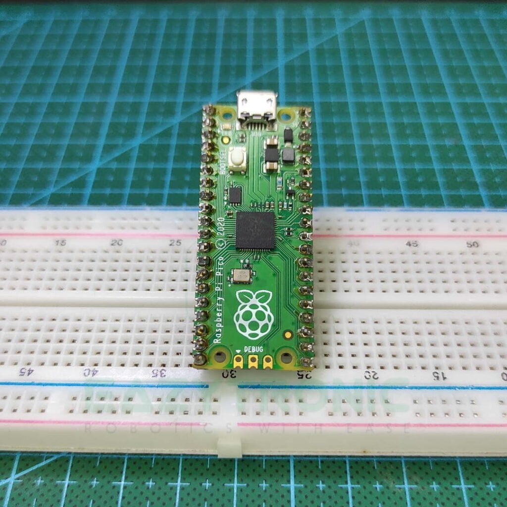
Raspberry Pi PICO is one of the trending microcontrollers used nowadays by many hobbyists and beginners. This board offers features that can give tough competition to ESP32 modules. Moreover, there is another version of this board that comes with Wi-Fi features. This enables it to use IoT devices and make some good stuff with them. Raspberry Pi Foundation has developed this board by keeping in mind the budget. Therefore, it comes under $5 which is very cheap for this many features. I have already covered a detailed article on this in Getting Started with Raspberry Pi PICO.
Additionally, the specs that rest within it are also crazy. It is built out of Dual-Core ARM Cortex M0+ paired with 264 KB of SRAM and 2 MB of FLASH storage, which is quite good at such a price point. Most importantly, it does not require and USB to Serial IC like on other boards, rather it has an inbuilt USB PHY1.1. This provides direct access to the chip in both BOOT mode and programming modes via Programming Environments like Thonny IDE and Arduino IDE. But like the coin has two sides, it also has some cons that can be a bit of trouble in some cases.
The GPIO pins available on the PI PICO are only 3.3 V tolerant. This is a kind of drawback for many sensor and devices that requires a 5V signal. Apart from this, it is a great alternative to Arduino Boards. Moreover, it can give good competition to the ESP32 boards. The other available version, PICO W is capable of using Wi-Fi along with all the features of its predecessor. Hence, this can also be used in making Many IoT projects.
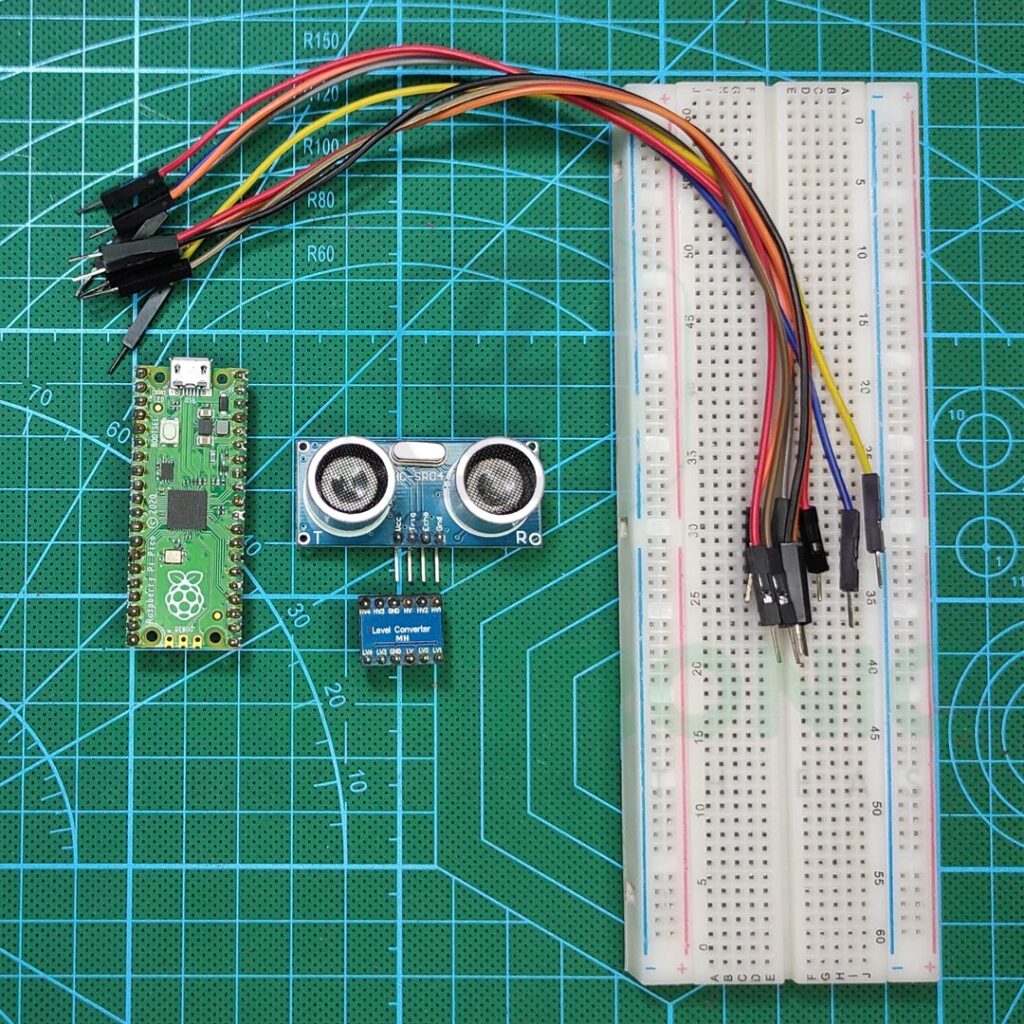
Material Required
The components we need to demonstrate this tutorial are very few and can be chosen upon the need and choices of the user. The link for components is provided below for online platforms.
- Raspberry Pi PICO or Pi PICO W
- HC-SR04, Ultrasonic Sensor
- Breadboard
- Jumper Wires
- Any object as Obstacle
- Working System for programming
Fritzing Schematic
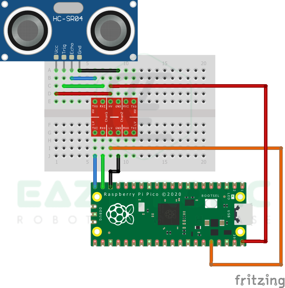
Wiring
| Pi PIPCO | HC-SR04 |
|---|---|
| VBUS | VCC |
| GND | GND |
| GPIO14 | TRIG |
| GPIO15 | ECHO |
NOTE:- I have used a logic level converter for converting the HC-SR04 Sensor logic level similar to Pi PICO. Therefore, pin mapping is somewhat confusing, but make sure to make the same to make the sensor work.
Programming Pi PICO with HC-SR04
Now comes the part of the article, programming Raspberry Pi PICO with HC-SR04 Ultrasonic Sensor in MicroPython. But before this, make sure to set up the Raspberry Pi PICO. A detailed tutorial on how to set up the Raspberry Pi PICO and more is given in the Getting Started with Raspberry Pi PICO. Now after setting up Pi PICO make sure to update all Pi PICO Board firmware to the latest version available. I’m using the Thonny IDE to do so. But you can also use Arduino IDE if you are using the C/C++ firmware. However, in C/C++ firmware you have to manually upgrade the firmware.
from machine import Pin,I2C
from utime import sleep_us,ticks_us
#initializing pin
echo=Pin(15,Pin.IN)
trig=Pin(14,Pin.OUT)
trig.value(0)
sleep_us(2)
#while loop condition
while True:
    try:
        trig.high()
        sleep_us(10)
        trig.low()
        while echo.value()==False:
            start_time=ticks_us()
        while echo.value()==True:
            stop_time=ticks_us()
        total_time=stop_time-start_time
        distance=(0.031594*total_time)/2
        print(distance)
    except KeyboardInterrupt:
        break
The complete code for the tutorial is provided above, as always it is advised to save it with some similar same as the tutorial. I’ve saved this code as hc_sr04.py. It is important to save the file with the .py extension, as without it the file will be saved as a normal text file. As a result, the code will not work. In addition to this, as mentioned in some previous articles that if you want to make Pi PICO, run this file as soon as the board start. Then save this file with main.py, or you can use another alternative by including this file name in the previously created main.py file. The common main file mentioned above works as an init file that runs the file whose name is mentioned in it.
Code Explanation
This is the main section for a beginner to learn how to code in MicroPython for Pi PICO. So, let’s begin, In the first line as always, we have imported some of the main modules which are required to interpret the code by the system. If you have operated HC-SR04 with Arduino, then you might not feel this code for so long. Because there is a library for this purpose. However, in Python, this library is not found. Either you have to make a custom module or use a few more lines of code in the same file. Moreover, in the Raspberry Pi with HC-SR04 I haven’t used any of the libraries, but rather some extra lines of code. You can read that article by clicking this link.
from machine import Pin,I2C
from utime import sleep_us, ticks_us
echo=Pin(15,Pin.IN)
trig=Pin(14,Pin.OUT)
trig.value(0)
sleep_us(2)In further lines, we initialize the pins that we’re going to use to interface Raspberry Pi PICO with HC-SR04. Instead of using the pins defined in the above code, you can change them according to your need. But in that case, make sure to connect the correct pins. Moreover, do not use any pins which are needed for the board to reset and cause any errors. Furthermore, we turn the trig pin of the sensor to LOW for 2 microseconds. This is the same as stated in the datasheet of the sensor to start the transmission process.
While loop
This is the main part of the code, it contains the main section which does all the conditional work. Now in the loop section, there are lines of code which in combination drivers the HC-SR04 and calculate the distances from the value received from it. I’ll add the comments in the code for more understanding. Anyhow, I’ll also explain the code here line by line, so let’s begin. In the first line of the code, we turn the HC-SR04 sensor TRIG pin high for 10 microseconds, as stated in the sensor datasheet. This will send a burst of Ultrasonic Sound waves for 10 microseconds. After this, we turn the pin low again, this makes the transmission of sound waves stop.
trig.high()
sleep_us(10)
trig.low()
while echo.value()==False:
    start_time=ticks_us()
while echo.value()==True:
    stop_time=ticks_us()
total_time=stop_time-start_time
distance=(0.031594*total_time)/2
print(distance)
Next, we check for the receiving pulse that came back after reflecting from the obstacle. Ultrasonic sound waves are then received by the sensor and according to this time calculated. As soon as the HC-SR04 starts sending the sound waves burst, it starts a timer. This timer waits for the sound waves burst to be received. With receiving, it marks the timer to stop and gives the amount of time taken by waves to echo back to the sensor. This time is pushed to the Microcontroller board we’re using in the form of pulses.
We check for these pulses and calculate time and further distance. Now for calculating the distance we need the speed of sound typically it is 340 m/s, but you can calculate it from here according to your area’s temperature as it affects the speed of sound. After this, all the code is just to calculate the distance and print it on the IDLE window.
With this, we mark the completion of the tutorial. For any issues or suggestions, comment down below.