
Hello tech freaks, I’m back with another interesting article, Raspberry Pi with HC-SR04. The ultrasonic sensor is one of the most common and very simple sensors to start with. Many development boards & microcontrollers can easily be hooked with the Ultrasonic sensor. Therefore, today I’ll be demonstrating Ultrasonic Sensor with Raspberry Pi via Python Code. But before that make sure to set up Raspberry Pi as explained in the Getting Started with Raspberry Pi article. Moreover, there are several versions of the Ultrasonic sensor, but I’ll be demonstrating it on the one I have. So let’s begin.
HC-SR04 Ultrasonic Sensor
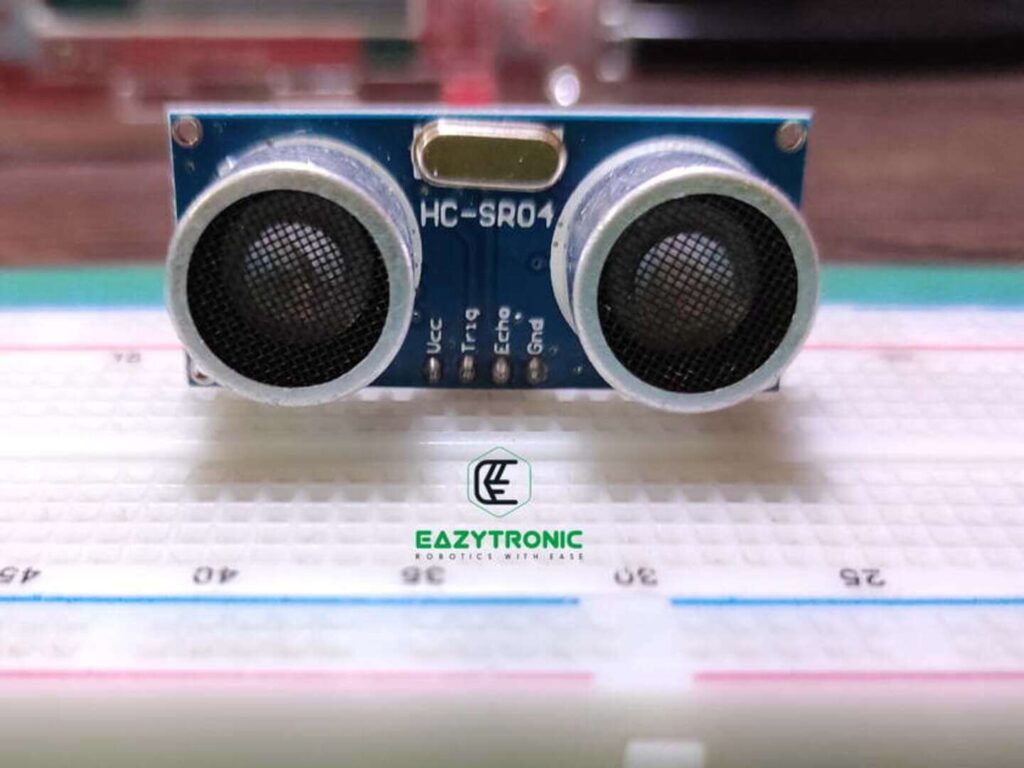
It is one of the best sensors for measuring distance and obstacles. Apart from the LIDAR sensor, this can be seen as a good alternative. Moreover, it is quite cheap, easily available, and above all can be programmed in many ways according to user needs. In one of the previous articles, I explained in detail about the HC-SR04 Ultrasonic Sensor, make sure to read it for more detail. However, a brief description of it is provided here. Ultrasonic Sensors work on the principle of Reflection of sound or Echo. Just like IR Sensor, it has components that transmit and receives ultrasonic sound waves to detect obstacle.
Besides detecting obstacles, it also measures distance, just like LIDAR in ship navigation. However, unlike them, it is not meant for professional work as it can only measure a distance of about 400 cm(4 m). Moreover, the distance it measures depends upon various climatic conditions like temperature and moisture. Therefore, while measuring distance using this, you have to take into consideration these conditions. Nevertheless, it is built of components that can be replaced to some extent, but SMD components need to be replaced with most care.
On the original Article page, I have already mentioned the assumed schematic of the Ultrasonic sensor. There I have explained how it works, but on contrary, I’ll do it here in brief. So, first, the transmitting signal is received from the microcontroller or development board to the 8-bit microprocessor which is on the Ultrasonic Sensor. This microprocessor controls everything from the timing to the filtering of the unwanted noise coming from the receiver end.
Raspberry Pi
Raspberry Pi SBCs are very famous among hobbyists and beginners. Not only do these boards offer a computer-like interface, but along with this, they come with GPIO pins. These GPIO Pins can be used to hook up different types of Sensors and devices, moreover, some display also uses these pins for communication and power. For complete detailed information regarding Raspberry Pi, including all versions, read the Getting Started with Raspberry Pi article. Nevertheless, I’ll explain this in brief here, that’ll cover all the main details about Raspberry Pi boards. But instead of explaining all the versions, I’ll be discussing the board I’m using to demonstrate today, i.e., Raspberry Pi 4B.
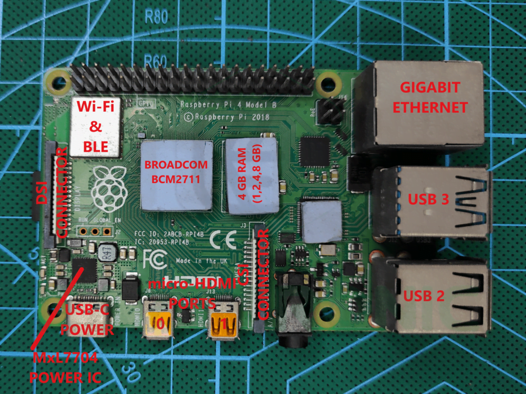
Raspberry Pi 4B is one of the most used SBCs for different projects and also for autonomous robots. To do all this, it comes with a Quad-Core Cortex A72 CPU paired with 1,2,4,8 GB of RAM according to the user’s requirement. In addition to this, it also comes with Dual-band Wi-Fi and Bluetooth 5.0 BLE. Not just this it also has 2 HDMI outputs, both can output 4K @ 60 FPS simultaneously. Lastly, it is also packed with USB 3.0 & USB 2.0. Apart from this, it also has a full 40-pin GPIO which can be sued to attach various devices and sensors to it without any problem.
GPIO pins are very useful, but they only have a voltage tolerance of 3.3V. Hence, the user must keep this in mind before attaching devices. Moreover, you can also use Logic level Shifter for using devices that are not on the same Logic Level. However, you can only use 3.3V output either Digital, Analog or PWM. This can’t be changed, and the same for the input, but you can always use a logic level shifter.
Material Required
Like other articles before, there are very few materials that are needed for this demonstration. These can be easily obtained in offline or online store and at cheap prices. However, I’ll still recommend you to go for offline stores
- Raspberry Pi 4B (4 GB)(Or any other compatible variant of Raspberry Pi SBC’s)
- Display with Keyboard and mouse or a headless setup
- HC-SR04 Ultrasonic Sensor
- Breadboard
- Jumper Wires
Frtizing Schematic
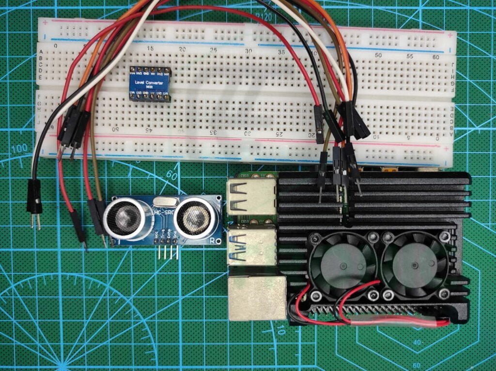
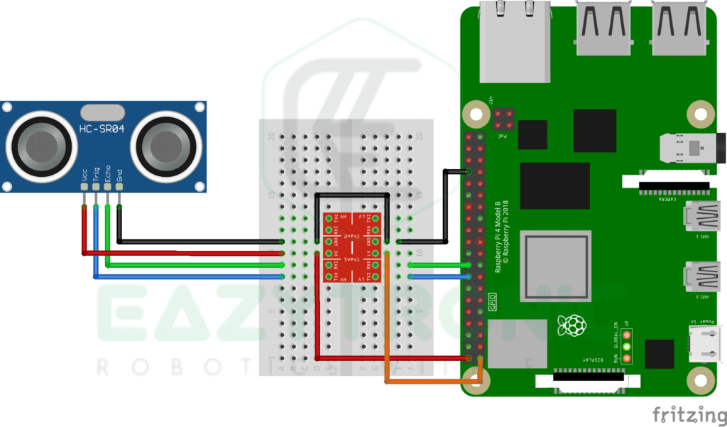
Below is the fritzing schematic, connect all the components as shown in the image below. However, if you make any change, then make sure to do the same in the code as directed further.
Wiring
| HC-SR04 | Raspberry Pi |
|---|---|
| VCC | 5V |
| TRIG | Pin 16/GPIO23 |
| ECHO | Pin 18/GPIO24 |
| GND | GND |
Programming Raspberry Pi with HC-SR04
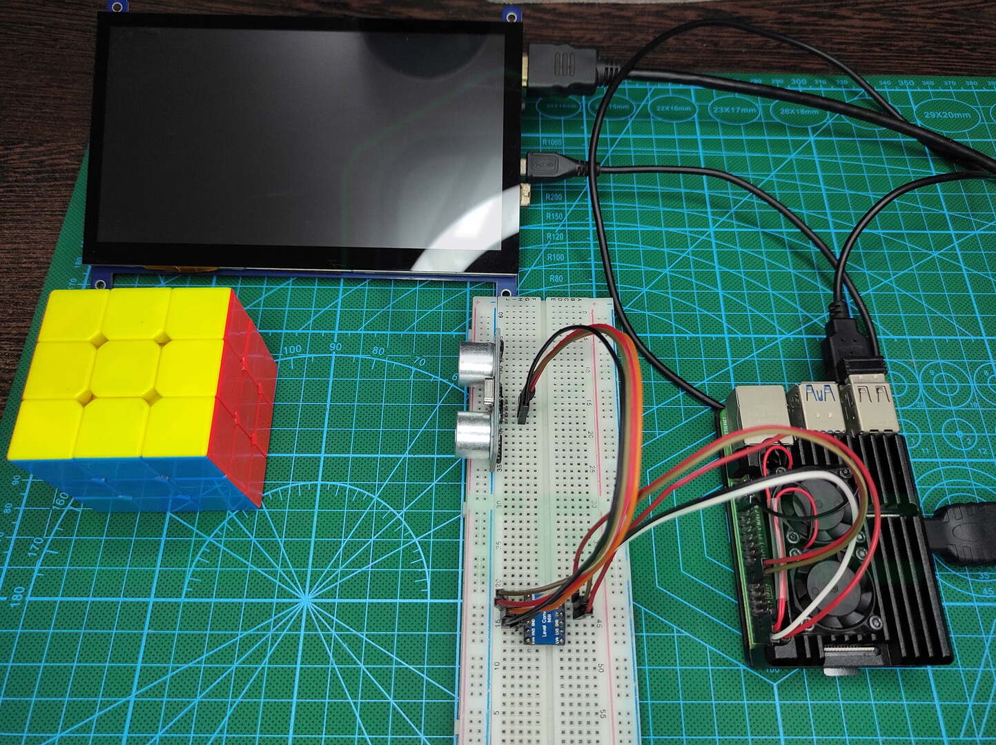
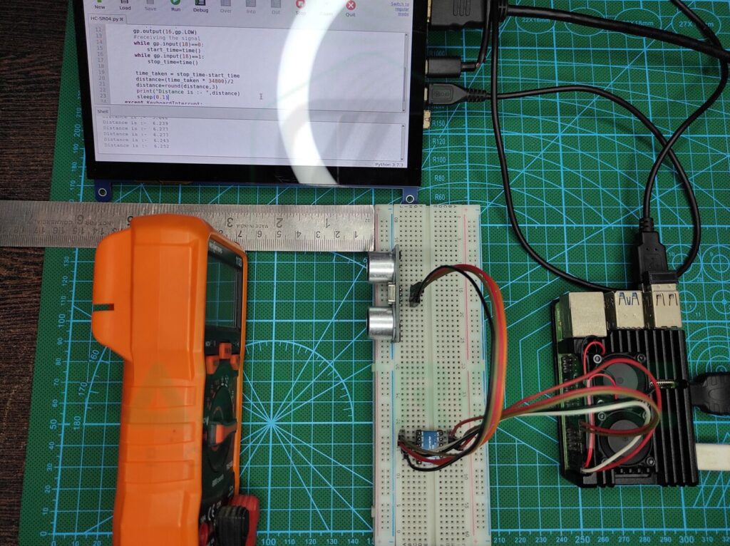
Let’s begin with the interesting part, i.e., programming Raspberry Pi to interface with HC-SR04. But before this make sure to set up the Raspberry Pi as mentioned in the Getting Started Raspberry Pi. Also, make sure to update the board definitions with the commands mentioned below. Along with this, I have also connected a 7-inch HDMI capacitive touch display to see, but you can also use the headless setup for this purpose via PuTTY. Moreover, if you want to keep it simple, then you can use any third-party remote desktop software like VNC Viewer and TeamViewer. Lastly, make sure to install the RPi.GPIO module, to enable the use of GPIO pins via python code.
sudo apt update
sudo apt-get full-upgrade
To install RPi.GPIO either download from the official website pypi.org. Or paste the below command in the terminal to download it.
pip install RPi.GPIOCode
import RPi.GPIO as gp
from time import sleep,time
gp.setmode(gp.BOARD)
gp.setup(16,gp.OUT)
gp.setup(18,gp.IN)
while True:
    try:
        gp.output(16,gp.LOW)
        sleep(0.002)    # 1 second = 1000000 microseconds, 2 microseconds = 0.000002
        gp.output(16,gp.HIGH)
        sleep(0.00001)     # 10 microseconds = 0.00001
        gp.output(16,gp.LOW)
        #receiving the signal
        while gp.input(18)==0:
            start_time=time()
        while gp.input(18)==1:
            stop_time=time()
        time_taken = stop_time-start_time
        distance=(time_taken * 34548)/2  # 34548 = speed of sound in cm/s with respect to the temperature
        distance=round(distance,3)
        print("Distance is :- ",distance)
        sleep(0.1)
    except KeyboardInterrupt:
        gp.cleanup()
        break
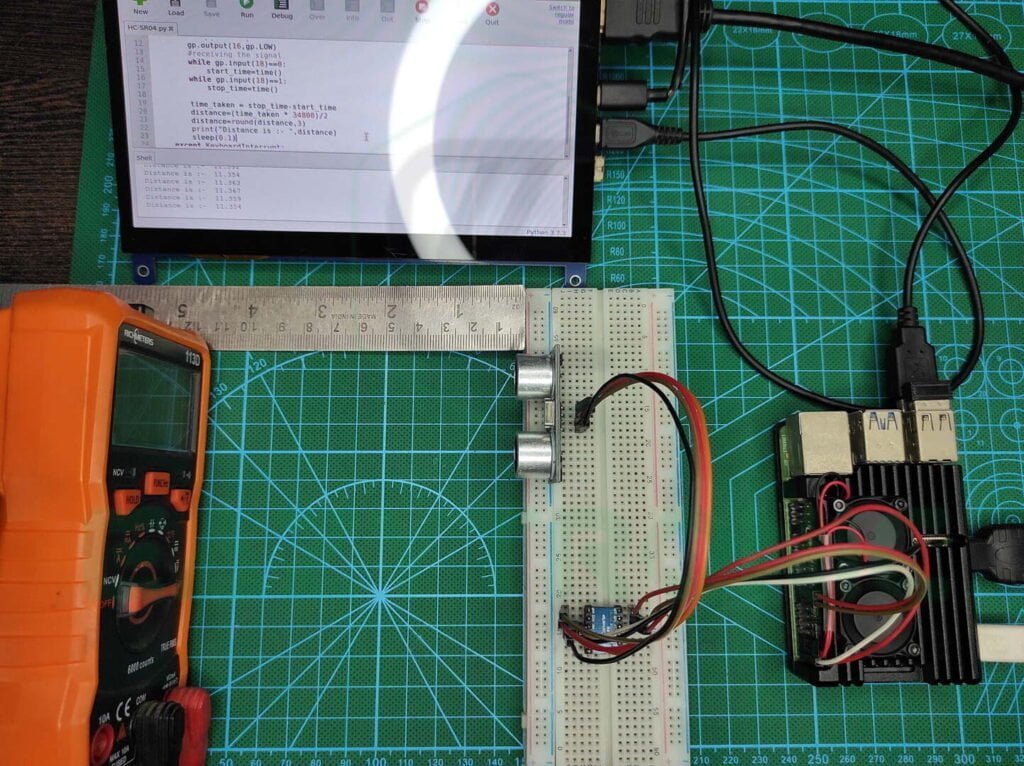
Above is the code for the HC-SR04 with Raspberry Pi. In this, I have used the IDLE window to print the distance measured by the Ultrasonic Sensor. Although this code works flawlessly yet if you stop it other than the keyboard interrupt, then it’ll show an error on the next restart. Moreover, you can also use a display or some sort of signal in combination with the code to make it more attractive to look at. In the coming article s, I’ll be explaining how to use various displays with Raspberry Pi & Raspberry Pi PICO. So, make sure to read the coming articles and learn to manipulate the code according to your needs.
In the code, I have added enough comments to make it more understandable, but if you didn’t understand any of the lines, then comment down below. Also, for more information about the working of the HC-SR04 Ultrasonic Sensor, read it corresponding article. However, the above code works correctly, but you have to make sure you enter the speed of sound correctly by measuring of according to the temperature in your area. You can easily do this by visiting this website and entering the temperature. In addition to this, it is advisable to enter the correct nearby temperature for best results.
Code Explanation
Now let’s see how the code exactly works, here I’ll try to explain most of the line of code but for modifications, you have to read the upcoming articles. Let’s start from the first line, In the First line, we import some important modules required for using the GPIO pins of Raspberry Pi boards. In the following line, we import sleep and time functions from the time module. These modules are required to perform operations on time-related arguments. The sleep function is used to perform a delay-like function as in Arduino IDE. Moreover, the time function is the same as the millis() function in Arduino IDE.
import RPi.GPIO as gp
from time import sleep,time
Next, we set the Board numbering method and initialize the pins. As mentioned in the Getting Started Article, where I have discussed both ways in which you can set the board numbering. Along with this, I have explained why I prefer board numbering, as it is quite easy to remember. Anyway, in the next line, we initialize the pin that we’ll be using for hooking up the HC-SR04 Sensor. If you have experience with Arduino IDE then you might know that while programming Arduino Board with HC-SR04 we use the library. That library restricts the distance to only 50 cm, whereas the total range is about 4 m.
gp.setmode(gp.BOARD)
gp.setup(16,gp.OUT)
gp.setup(18,gp.IN)
While Infinite loop
Next comes the while loop, we have made the condition that makes the loop run infinitely. Like other codes in the Python language, I usually prefer an infinite loop with a terminating statement. I have made the loop in such a way that it prints the distance on the IDLE window. You can change this with some sort of TFT display for a more attractive look. Furthermore, we implement the try and except method for making the loop run until the terminating statement strikes. For termination of the loop, i.e., exception, we use the Keyboard Interrupt (Ctrl+ C).
gp.output(16,gp.LOW)
sleep(0.002)    # 1 second = 1000000 microseconds, 2 microseconds = 0.000002
gp.output(16,gp.HIGH)
sleep(0.00001)     # 10 microseconds = 0.00001
gp.output(16,gp.LOW)
In the first line in the while loop, we give a low signal to the TRIG pin of the HC-SR04 Ultrasonic Sensor. Just like the Arduino Library and Datasheet for HC-SR04, we pull the TRIG pin of the sensor LOW for 2 microseconds. Because in python delay is measured in seconds, hence we have to write precisely or 2 microseconds. Next as stated in the Datasheet we make the TRIG pin HIGH for 10 microseconds to send a pulse of ultrasonic sound. After then, pull the TRIG pin to LOW until the next cycle.
while gp.input(18)==0:
    start_time=time()
while gp.input(18)==1:
    stop_time=time()
distance=round(distance,3)
print("Distance is :- ",distance)
sleep(0.1)
In the next few lines, we check for the echo received by the transducer, and as soon as the signal coming from the ECHO pin goes high. The Raspberry Pi checks the time of the system as in the above code. Similarly, when the signal becomes low, it again checks time and finally calculates the total time by subtracting the final & initial time. Then, using the simple formula of distance = speed x time, we calculate the time.
With this, we have completed the Raspberry Pi with HC-SR04 Ultrasonic Sensor. It is quite detailed but anyway if you feel something is missing or face any issues comment down below. I’ll resolve it ASAP.