
Hey Folks, Welcome to another interesting article on Raspberry Pi with IR Sensor. An IR Sensor is one of the most basic sensors with which a beginner may start. In addition to this, there are many other microcontrollers and development boards that can be hooked to it. Today we’ll be doing Raspberry Pi interfacing with IR Sensor, also there will be a complete explanation of the code. In a previous article, I have already explained IR Sensors in detail. Same for the Raspberry Pi, make sure to read them for complete information. Let’s begin today’s article.
IR Sensor
Ir sensor is one of the most interesting sensors of all, due to its simple construction and ease to use, it is ideal for beginners to start with. Many high-level projects can be built using this sensor like line follower, obstacle avoiding, and many others. However, it is impossible to do so without prior knowledge of the sensor, so make sure to read the introductory article on IR Sensor. I have already explained in detail all the necessary information about the sensor.
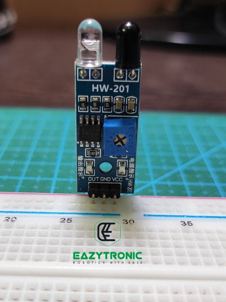
Nevertheless, I’ll explain in brief about IR sensors here also. IR sensor is based on the phenomena of Reflection of light. The light here used is Infrared light, which is out of the visible spectrum. There is an IR Light emitter and a photodiode attached in front of the sensor. These are used for the main purpose along with other components. It is available in two different versions, mainly that are based on different IC. LM393 & LM358 are the two ICs that are used mainly. These are Low-Power Dual Voltage Comparator and Low-Power Dual Operational Amplifier, respectively.
There is also a potentiometer to trim the values of the sensor. On the other hand, in most of the versions, there is only digital output. Therefore, the potentiometer is used to trim the range of the sensor indirectly. In addition to this, try not to put the sensor in front of bright light sources like fire and direct sunlight. These sources also have Infrared Light that can lead to malfunction of the sensor. Moreover, don’t put the sensor in front of dark color objects, (i.e., black shades) as those objects absorb all the infrared light. Hence, resulting in a malfunction of the sensor.
Raspberry Pi
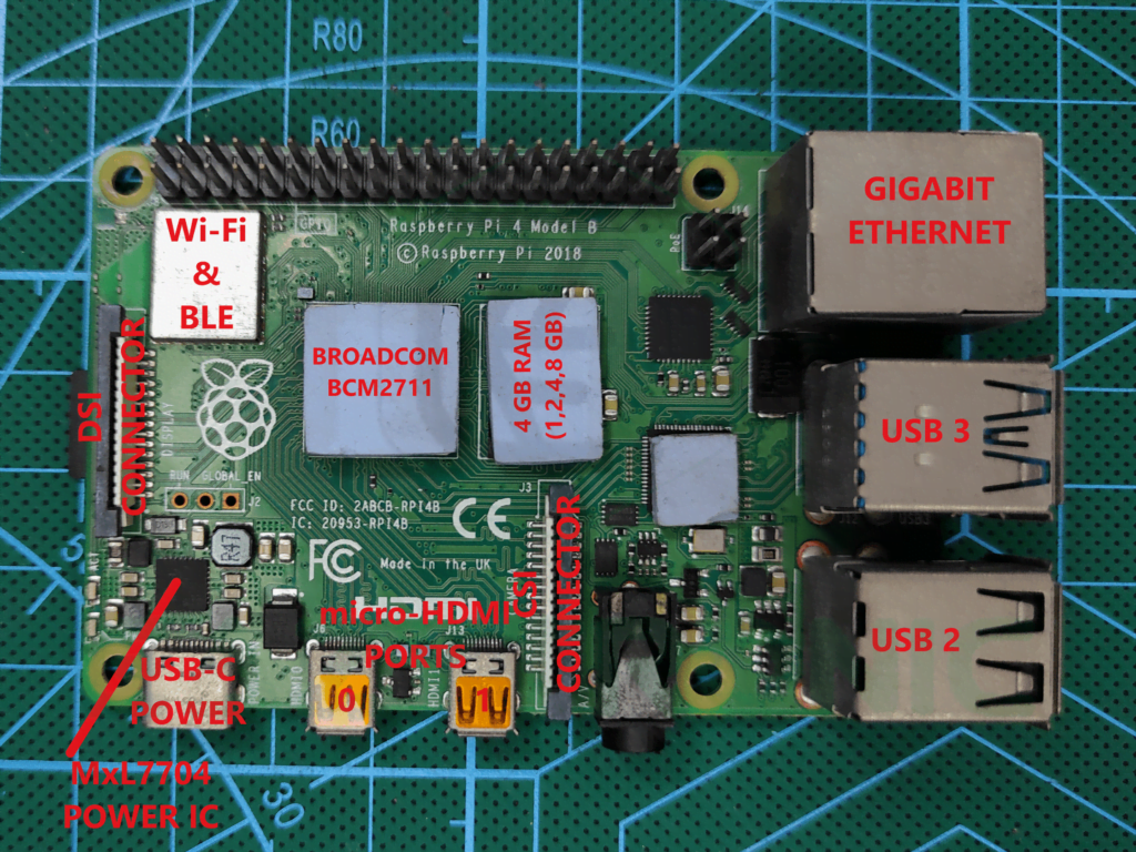
Raspberry Pi, one of the most popular SBCs, is the heart of this tutorial. Over time, we have seen many versions of the Raspberry Pi, which got advanced subsequently. Today we’ll be using Raspberry Pi 4B, 4 GB variant, I also have Raspberry Pi 3 whose code will also be available below. Raspberry Pi Boards are usually SBC for low to mild computing, and obviously cannot be compared with modern systems. However, it is still as much power as your mid-range android device. Moreover, it supports all the capabilities a PC or laptop should have and support many OS of user choice.
A complete detailed introduction article for Raspberry Pi Board has already been posted on our site, make sure to read it. Nevertheless, I’ll discuss some of its common features here also. Raspberry Pi Boards come with up to 1.5GHz Quad-Core CPU. Paired with 1 GB, 2 GB, 4 GB, 8Gb choices of RAM, for storage you can either use an SD Card or a disk drive via USB port. As for me, I have Raspberry Pi 4B 4 GB variant and for storage, I use a 64 GB Samsung EVO plus SD Card. I also have many other OS installed on different SD Cards, but it depends on user choice.
Lastly, these boards also have a 40-pin GPIO connector for connecting peripherals like sensors and other devices. These pins can support all types of communication, as mentioned in the introductory article. Moreover, you can also connect two different displays along with a camera.
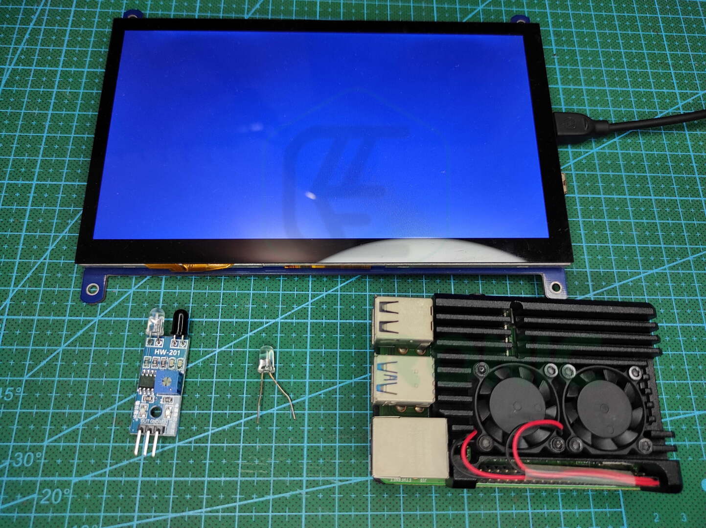
Material Required
The material which we require for this tutorial is simple and easy to find. Below is also the buy link to some components.
- Raspberry Pi Board (Pi 4B or Pi 3B+)
- Display with Keyboard & mouse or use headless setup
- Bread Board
- IR Sensor
- LED with 1k resistor
- Jumper wires
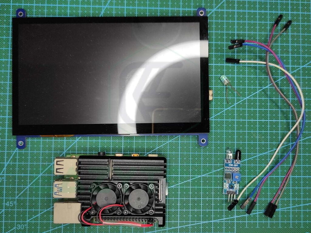
Fritzing Schematic
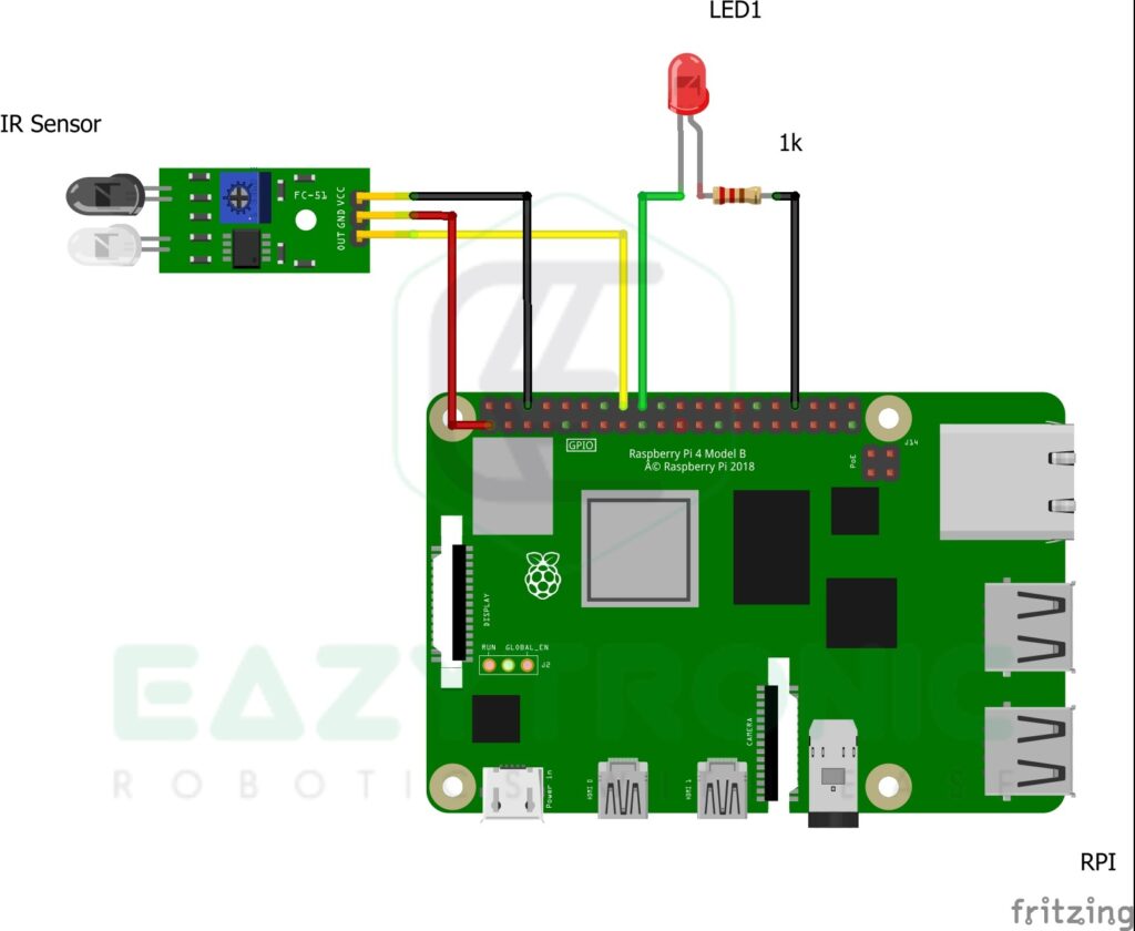
Below is the Fritzing schematic along with the pinout, make sure to connect the same as shown or change in code for pins of your choice.
Wiring
| IR Sensor | Raspberry Pi 4B |
|---|---|
| VCC | 3V3 |
| GND | GND |
| OUT | pin 16/GPIO 23 |
Also connect a LED to GPIO of Raspberry Pi with 1K resistor in series.
Programming Raspberry Pi with IR Sensor
Now, this is interesting, we have come to the main section of the article. Before this, you have to set up the Pi, as I have done in the Getting Started Raspberry Pi article. On the other hand, you can also set up the Pi in a headless way, which means you can control it via a terminal over the internet. For this, you need to download PuTTY which is a great software for this purpose. Also, you can use any remote control software like VNC and TeamViewer, which are also great alternatives. Overall, in simple words, you need to install an OS on Pi and set it up.
import RPi.GPIO as gp
from time import sleep
gp.setmode(gp.BOARD)
gp.setup(16,gp.IN)
gp.setup(18,gp.OUT)
while True:
try:
gp.output(18, not gp.input(16))
except KeyboardInterrupt:
gp.cleanup()
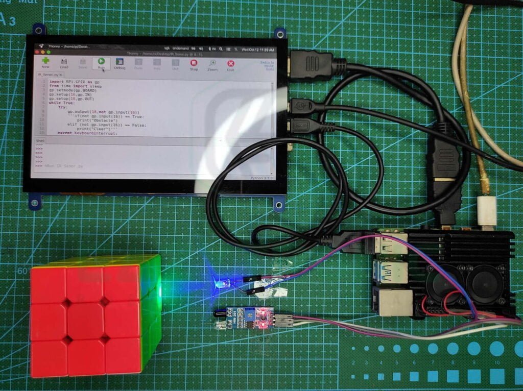
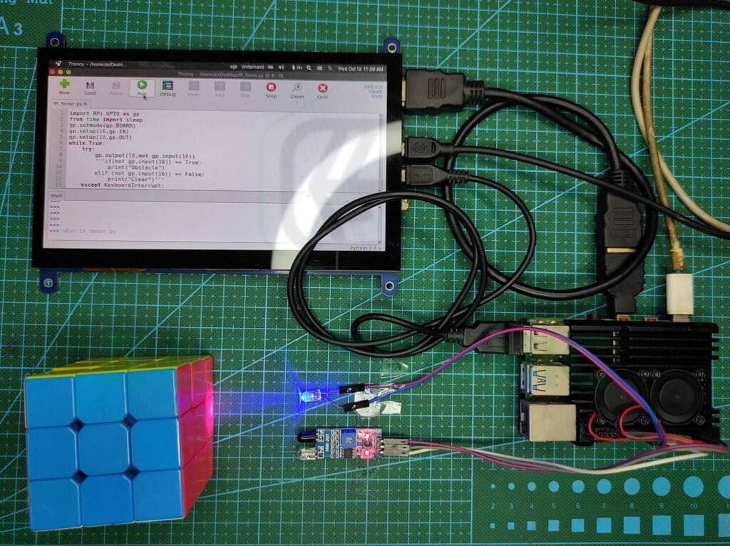
breakAbove is the code which reacts with the LED according to the input of the IR Sensor. To run this code, you have to open a blank file in Thonny IDE as shown below. As I have Twister OS installed, I’ll show you that, you may open Thonny from your selected OS. You can also use the terminal for this purpose, as for a headless setup. Commands for creating a file using the terminal are mentioned below. Moreover, in the future, I’ll also add support for the git library, so it’ll be easy to use for beginners. Unlike Raspberry Pi PICO with IR Sensor, there is no compulsion for saving the file with a certain main. Hence, you can save the file with any name and run it accordingly.
Code with Blinking LED
Below is the code without the LED Blink, it simply prints the status of the sensor on the IDLE window as shown in the image below. Moreover, you can also use this code if you want to integrate it with something else. In addition to this, code is a separate code, which can be imported into other files for use. On the other hand, as stated before, if the version of the sensor is different from the one I’m currently using changes the output will change accordingly. Furthermore, you can also change the pin on which the sensor is attached, but unfortunately, you cannot hook up any Analog device directly. As there are no analog pins available on the Raspberry Pi 4, so you have to use an ADC module for this purpose.
import RPi.GPIO as gp
from time import sleep
gp.setmode(gp.BOARD)
gp.setup(16,gp.IN)
while True:
    try:
        if (not gp.input(16)) == True:
            print("Obstacle")
        elif (not gp.input(16)) == False:
            print("Clear")
    except KeyboardInterrupt:
        gp.cleanup()
        break
Code Explanation
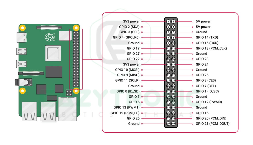
Now here comes the interesting part, code explanation. Although the tutorial is very simple for beginners, let me explain it for the first time. In the first line, I have imported RPi.GPIO module to use the GPIO pins of the Raspberry Pi 4. It is the same for the Raspberry Pi 3, but the Raspberry version below may require some other. In addition to this, you can also check the pinout of the GPIO of your board either from this link or type the pinout in the terminal. Below is the image for the reference pinout of the Raspberry Pi 4B model. Moreover, you can also read the Getting started Raspberry Pi Article for more detailed information.
import RPi.GPIO as gp
from time import sleep
gp.setmode(gp.BOARD)
In the first line, we import the main module that enables us to use the GPIO pins of the Raspberry Pi Boards. This module can be different according to the board and user preference, but most commonly this one is used. Next, we import the sleep module from the time that allows us to give a delay in the program. This function takes time in seconds(s). Therefore, make sure to enter the values in the correct format like 1s → 1, 100 milliseconds → 0.1. Unlike the Raspberry Pi PICO, you cannot use the sleep_ms module in this, instead, you have to adjust it to the correct time frame.
Furthermore, we set the mode in which the interpreter identifies the pin we initialize of the Raspberry Pi. You can choose from the two modes available, namely BOARD and BCM. BOARD refers to the pin numbering starting from left to right and top to bottom, relative image is attached below. BCM refers to the GPIO pins according to the Datasheet of the Raspberry Pi. However, I find it sometimes hard to remember the GPIO numbering, thus I use BOARD mode for easy pin count. The below-attached image has pin numbering according to both.
Pin Assignment
#syntax RPi.GPIO.setup(<pin number>, RPi.GPIO.<pinmode>)
gp.setup(16,gp.IN)
gp.setup(18,gp.OUT)
In further lines, we initialize the pins which we’re going to use in our project. During initialization, you can set the initial or default state of the pin also. Although, you have to clear the GPIO pins at the end to avoid warning in the IDLE window. For pin assignment, we also use the syntax mentioned above. After the pin mode, you can also add the default state of the pin as stated above.
While infinite loop
Next is the while loop with the try and except method, it is an infinite loop that has a terminating line or condition given the exception block of the code. While the loop contains the main code that can be modified according to the user’s needs. However, currently, in both codes, there is very simple lines of code are used. In the Responsive LED code, which reacts to the output from the IR Sensor, we read the input signal and according to it change the state of the LED. On the other hand, in simple IR Sensor code, we read the input and accordingly print the status of the signal coming from the IR Sensor.
As mentioned in the IR Sensor intro article, and Pi PICO with IR Sensor, there are two types of IR Sensor that give opposite outputs to each other. Therefore, the code will change completely, but nothing to worry code for them is also given below. However, you have to make sure of the type of IR Sensor you are using before running the code.
import RPi.GPIO as gp
from time import sleep
gp.setmode(gp.BOARD)
gp.setup(16,gp.IN)
gp.setup(18,gp.OUT)
while True:
    try:
        gp.output(18, not gp.input(16))
    except KeyboardInterrupt:
        gp.cleanup()
        break
import RPi.GPIO as gp
from time import sleep
gp.setmode(gp.BOARD)
gp.setup(16,gp.IN)
while True:
try:
if (not gp.input(16)) == True:
print("Obstacle")
elif (not gp.input(16)) == False:
print("Clear")
except KeyboardInterrupt:
gp.cleanup()
break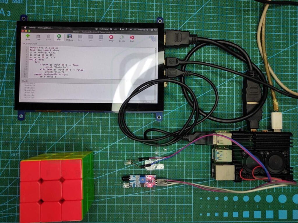
With this, we have completed Raspberry Pi with IR Sensor article. I hope you like It, However, for any other details or corrections comment down below.